
Branch pipe

A branch pipe and branch technology, applied in the field of branch pipes, can solve problems such as difficult construction and inconvenient use of branch pipes, and achieve the effect of convenient use and easy setting operations

Inactive Publication Date: 2018-12-04
KAKINUMA KINZOKU SEIKI
View PDF9 Cites 1 Cited by
  • Summary
  • Abstract
  • Description
  • Claims
  • Application Information

AI Technical Summary

Problems solved by technology

[0005] The axial center deviation O', O" means that the positions of the pipes passing through the floor and ceiling of each floor are different, making construction difficult, and the above branch pipes are inconvenient to use.

Method used


Image

  • Branch pipe
  • Branch pipe
  • Branch pipe

Examples


Embodiment Construction

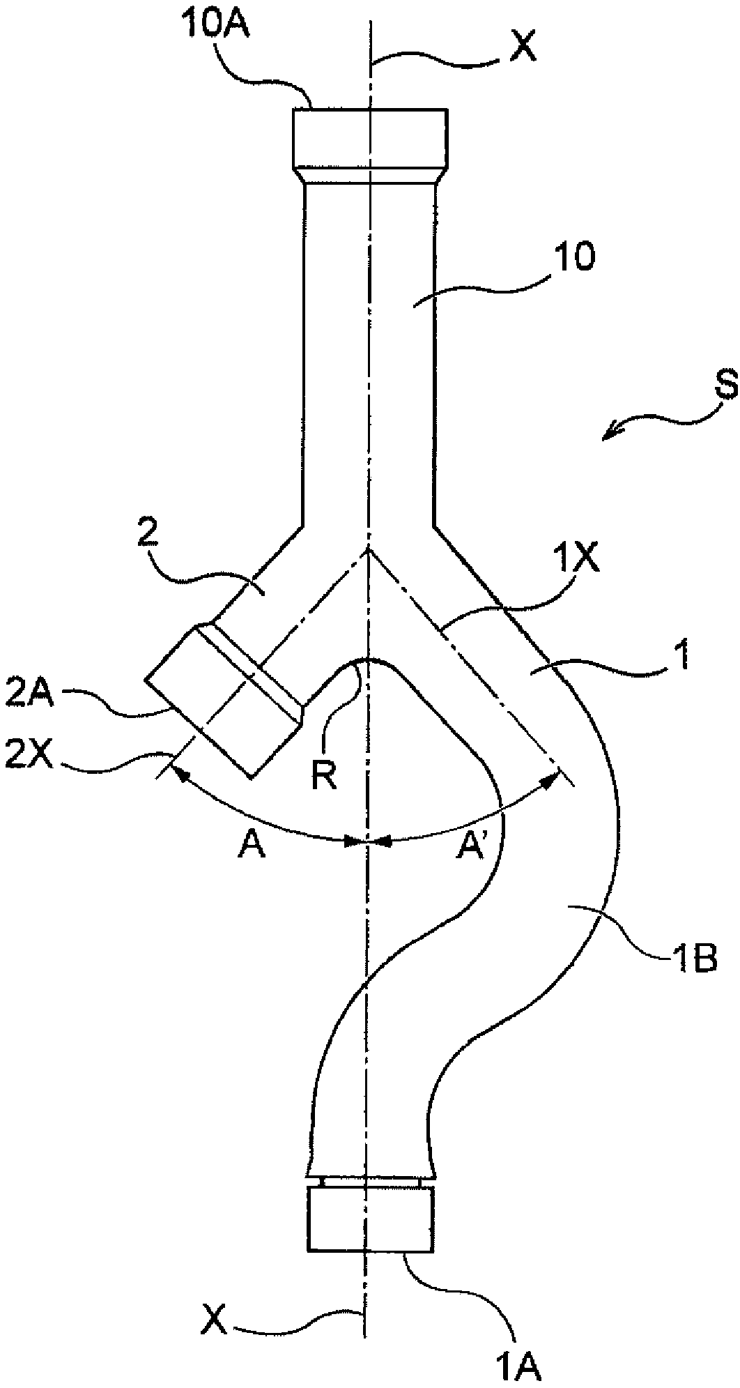
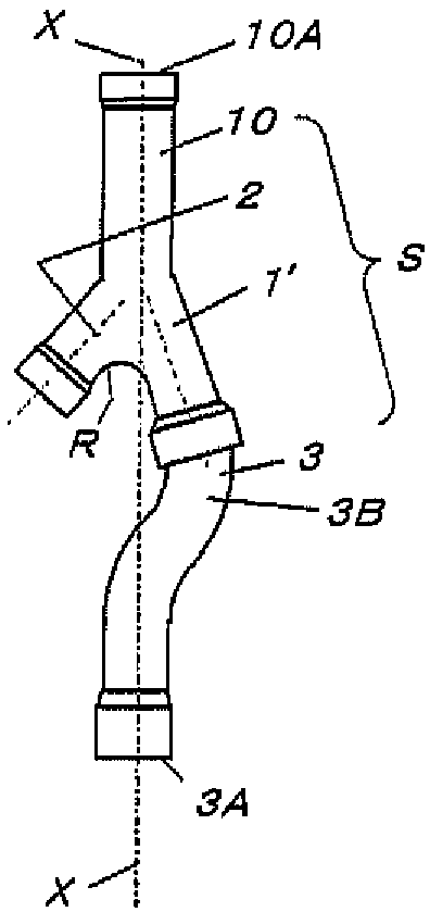
[0041] Referring to the accompanying drawings ( figure 1 and figure 2 ) describes a branch pipe according to an embodiment of the present invention.

[0042] figure 1 It is a schematic diagram showing the branch pipe S of the present invention. The branch pipe S is a branch pipe that branches the fluid from the inflow part 10 to the first outflow part 1 and the second outflow part 2, and is assembled to a multi-type air conditioner, for example. Refrigeration cycle system, used when the refrigerant is divided.

[0043] The middle of the first outflow part 1 is bent so that the axis X of the tube 1A on the outlet side of the first outflow part 1 coincides with the axis X of the tube 10A of the inflow part 10 . figure 1 1B shown is the bend.

[0044]In this way, the pipe 10A of the inflow part 10 and the pipe 1A on the outlet side of the first outflow part 1 can be located on the same axis X. Therefore, for example, a multi-type air conditioner is installed in a room of ...


PUM


Abstract

The invention aims to provide a branch pipe good in usage convenience. The branch pipe (S) branches fluid from an inflow portion (10) into a first outflow portion (1) and a second outflow portion (2).The middle portion of the first outflow portion (1) is curved so that the axis of the pipe at the outlet of the first outflow portion (1) is aligned with the axis of the pipe of the inflow portion (10).

Description

technical field [0001] This invention relates to branch pipes, and more particularly to good branch pipes which are convenient to use. Background technique [0002] In the past, in the multi-type air conditioner, in order to branch the refrigerant, use Figure 10 Branch pipe S' shown. [0003] Figure 11 The described structure is, for example, a structure in which indoor units of a multi-type air conditioner are installed on each floor, and four branch pipes S' are connected in series. [0004] Therefore, in the case of using the above-mentioned branch pipe S', the axial center deviation O', O" will generate (L / 2)×3. [0005] The axial center deviation O', O" means that the positions when the pipes pass through the floor and ceiling of each floor are different, making construction difficult, and the above-mentioned branch pipes have a problem that it is inconvenient to use. Contents of the invention [0006] An object of the present invention is to provide a branch pip...

Claims


Application Information

Patent Timeline
Patent Type & Authority Applications(China)
IPC IPC(8): F25B41/00F25B41/42
CPCF25B41/00F25B41/42F25B41/40F16L41/023F25B2500/01F16L59/163F16L59/182F16L41/021
Inventor 柿沼收
Owner KAKINUMA KINZOKU SEIKI
Learn More