Illumination system comprising ceramic luminescence converter

A light-emitting converter and lighting system technology, applied in the field of lighting systems, can solve the problems of opacity, insufficient color reproduction, and unusability of inorganic light-emitting materials

Inactive Publication Date: 2008-01-09
KONINK PHILIPS ELECTRONICS NV
View PDF2 Cites 12 Cited by
  • Summary
  • Abstract
  • Description
  • Claims
  • Application Information

AI Technical Summary

Problems solved by technology

[0007] However, there has been a problem in prior art lighting systems containing microcrystalline phosphors: the opacity of the phosphor prevents it from being used in many applications
[0009] However, prior art solutions for lighting systems with enhanced transparency suffer from insufficient color reproduction

Method used


Image

  • Illumination system comprising ceramic luminescence converter
  • Illumination system comprising ceramic luminescence converter
  • Illumination system comprising ceramic luminescence converter

Examples


specific Embodiment

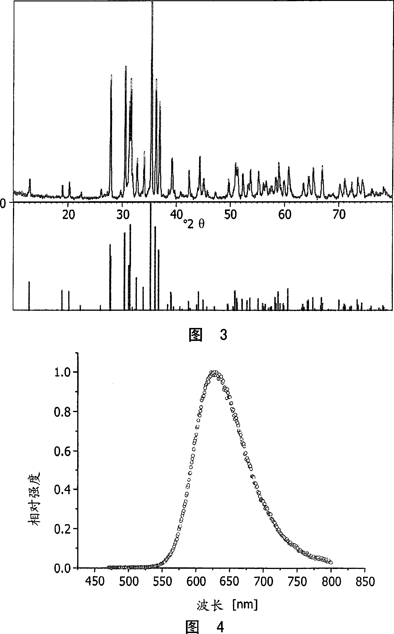
[0050] The following amounts of strontium carbonate and europium oxide are thoroughly dry mixed:

[0051] SrCO 3 :20.0g

[0052] Eu 2 O 3 :0.487g

[0053] The mixture was placed in an alumina crucible and calcined at 1200°C for 2 hours in reducing air, which was a composition of nitrogen containing 5% (volume ratio) hydrogen. After cooling to room temperature, the obtained powder block was crushed into fine powder under dry nitrogen in a glove box.

[0054] The following amounts of the resulting mixed oxide powder and silicon nitride powder were wet mixed together in dry acetone.

[0055] (Sr, Eu)O: 5.0g

[0056] Si 3 N 4 :3.77g

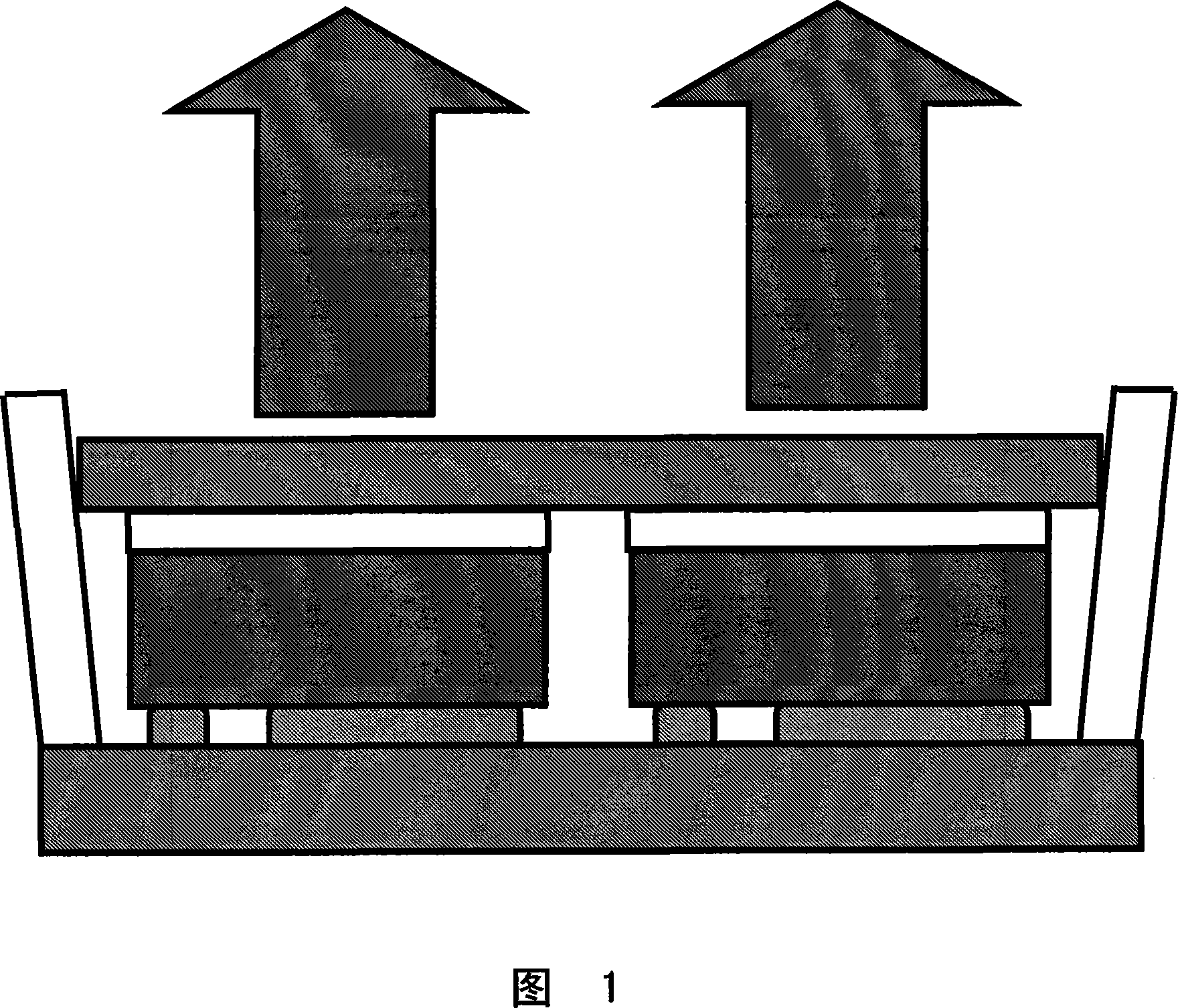
[0057] After the powder mixture was dried by evaporation of acetone, it was placed in an alumina crucible and fired in reducing air containing 5% (volume ratio) of hydrogen in nitrogen at 1550°C for 2 hours. The original phosphor powder was mixed with an organic glycol binder, pressed into small balls, and passed at 44800Psi (3.091×10 8 N / m 2 ) Under col...


PUM

PropertyMeasurementUnit
spectroscopyaaaaaaaaaa

Abstract

An illumination system, comprising a radiation source and a monolithic ceramic luminescence converter comprising at least one phosphor capable of absorbing a part of light emitted by the radiation source and emitting light of wavelength different from that of the absorbed light; wherein said at least one phosphor is an europium(II) - activated oxonitridoaluminosilicate of general formula EA2-zSi5-aAlaN8-bOb:Euz wherein 0< a < 4, 0< b < 4 and 0 < z < 0.2; EA is at least one earth alkaline metal chosen from the group of calcium, barium and strontium provides a system with a converter that is effective for conversion of high energy radiation, such as radiation in the UV to blue range of the electromagnetic spectrum. . It is also effective, as it is a good transmitter of the light energy, that results from the conversion of the high energy radiation input. Otherwise the light would be absorbed in the material and the overall conversion efficiency suffers. The invention is also concerned with a monolithic ceramic luminescence converter comprising at least one phosphor capable of absorbing a part of light emitted by the radiation source and emitting light of wavelength different from that of the absorbed light; wherein said at least one phosphor is an europium(II) -activated oxonitridoaluminosilicate of general formula EA2-zSi5-aAlaN8-bOb:Euz wherein 0< a < 4, 0< b < 4 and 0 < z < 0.2; EA is at least one earth alkaline metal chosen from the group of calcium, barium and strontium.

Description

Technical field [0001] The present invention generally relates to a lighting system including a radiation source and a ceramic luminescence converter (ceramic luminescence converter). The invention also relates to ceramic luminescence converters used in such lighting systems. [0002] In particular, the present invention relates to a lighting system and a ceramic luminescence converter for generating specific, colored light (including white light) through down-conversion luminescence based on a radiation source emitting ultraviolet or blue radiation and additive color mixing (additive color mixing) . In particular, it is conceivable to use light emitting diodes as a radiation source. Background technique [0003] Recently, various attempts have been made to manufacture a white light illumination system by using light emitting diodes as a radiation source. When red, green, and blue light emitting diodes are used to generate white light, there is a problem that white light of ideal...

Claims


Application Information

Patent Timeline
Patent Type & Authority Applications(China)
IPC IPC(8): C09K11/77C09K11/78C09K11/79C09K11/80H01L33/50
CPCH01L33/504H01L33/502C09K11/0883C09K11/7731C09K11/7734C04B35/5935C04B35/597C04B35/6265C04B35/6268C04B35/62685C04B35/6455C04B2235/3208C04B2235/3213C04B2235/3215C04B2235/3224C04B2235/3873C04B2235/652C04B2235/6582C04B2235/77C04B2235/9653H01L2224/13H01L2924/00014H01L2924/00011C09K11/77347C09K11/77342C09K11/77348H01L2224/0401
Inventor P·施米特W·布塞尔特S·戈尔施
Owner KONINK PHILIPS ELECTRONICS NV
Why Eureka
Try Eureka