
Multi-room type air-conditioning device

A multi-chamber, air conditioner technology, applied in space heating and ventilation, heating methods, lighting and heating equipment, etc., can solve problems such as hindering the rise of condensing temperature, unable to recover oil when recovering refrigeration oil, and difficult to recover.

Active Publication Date: 2008-01-16
PANASONIC CORP
View PDF1 Cites 23 Cited by
  • Summary
  • Abstract
  • Description
  • Claims
  • Application Information

AI Technical Summary

Problems solved by technology

[0004] However, in the above-mentioned conventional air conditioner, when the compressor is started in the heating operation state, the refrigerant in the stopped indoor unit also flows and releases heat, which hinders the increase of the condensing temperature in the initial stage of the heating operation.
Moreover, since the opening of the expansion valve will be corrected at the same time when starting, it is impossible to correct the difference in installation conditions such as the difference in the easy accumulation of refrigerating machine oil caused by the difference in the distance between the indoor unit and the outdoor unit, and the Considering the ease of storage of refrigerating machine oil due to the difference in height between units, the difference in room temperature of each indoor unit, the difference in the elapsed time after the start of operation, and the state of refrigerating machine oil stored in the indoor unit, there will be relatively close Although the refrigerating machine oil in the remote indoor unit can be recovered smoothly, it is difficult to recover the refrigerating machine oil in the remote indoor unit, or the oil cannot be recovered when the refrigerating oil must be recovered during operation
In such a case, the compressor is likely to fail

Method used


Image

  • Multi-room type air-conditioning device
  • Multi-room type air-conditioning device
  • Multi-room type air-conditioning device

Examples


Embodiment 1

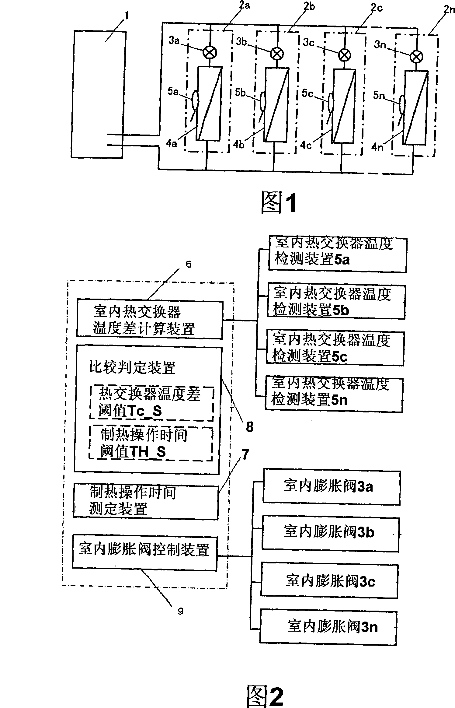
[0027] Fig. 1 is a schematic structural diagram of an air conditioner according to Embodiment 1 of the present invention. As shown in Fig. 1, multiple indoor units 2a, 2b, 2c, ... 2n (n is an arbitrary number, the same below) are connected to the outdoor unit 1, and indoor expansion valves 3n are respectively installed in each indoor unit 2n. In addition, an indoor heat exchanger temperature detection device 5n is attached to each indoor heat exchanger 4n.

[0028] When the above-mentioned refrigeration cycle performs heating operation, the refrigerant first flows from the outdoor unit 1 into multiple indoor units 2n, then releases heat in the indoor heat exchanger 4n, then passes through the indoor expansion valve 3n, and finally returns to the outdoor unit 1 middle. Each indoor unit 2n can be individually operated or stopped, and each indoor unit 2n is controlled such that when the compressor is stopped (after reaching the set temperature) or when the heating operation is s...

Embodiment 2

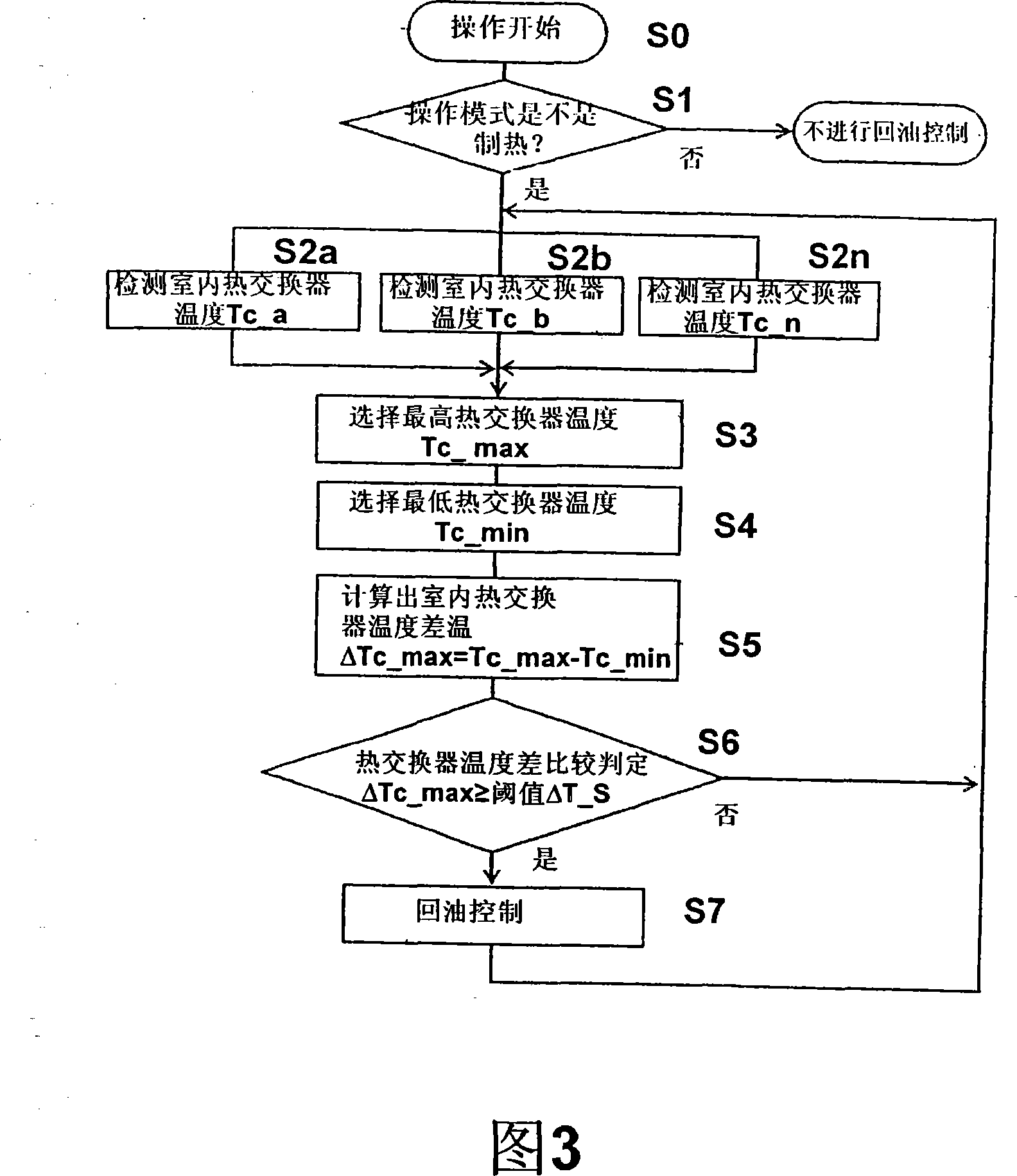
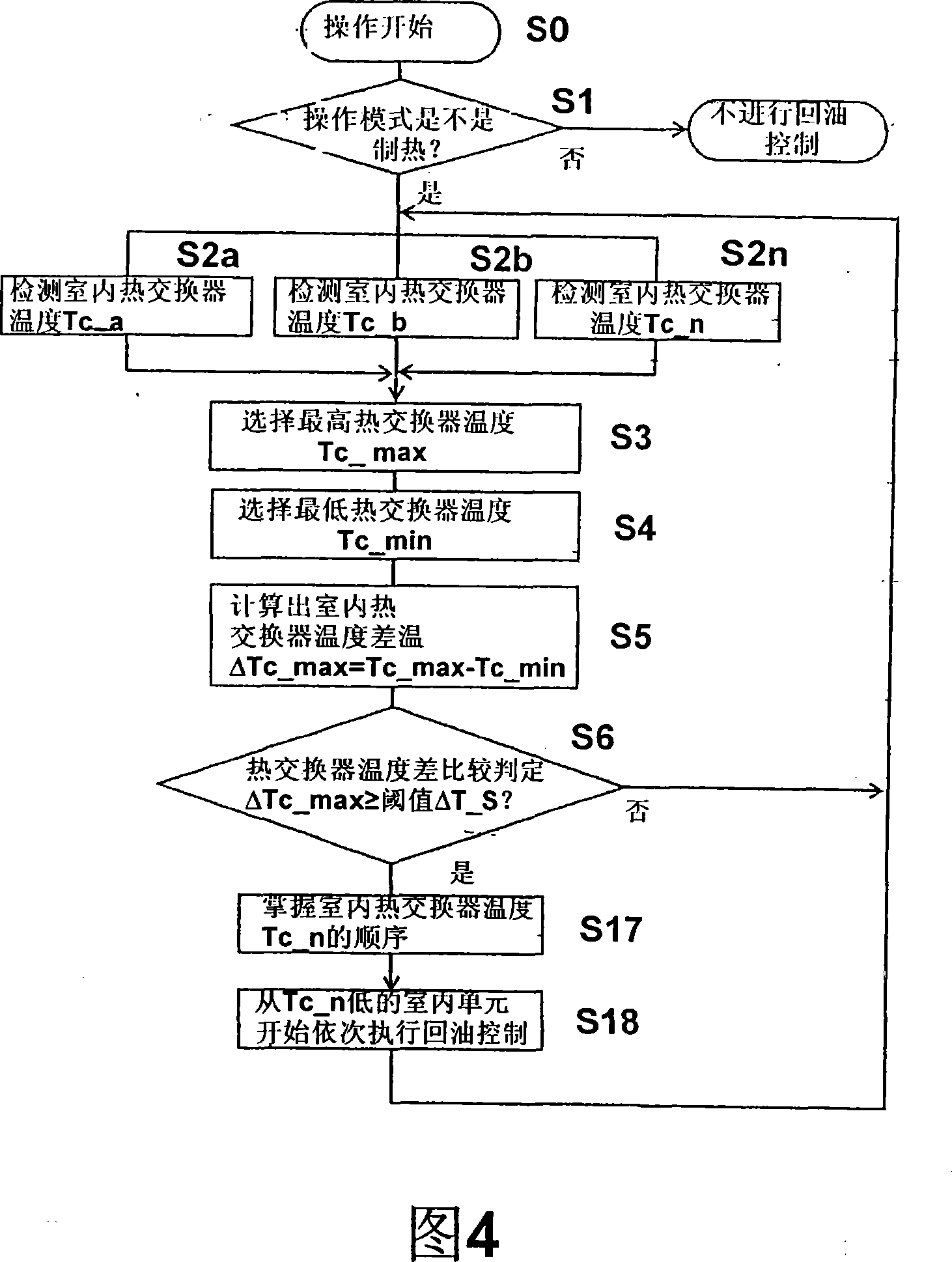
[0038] Fig. 4 is a flow chart of the oil return control of the air conditioner in Embodiment 2 of the present invention. The operation and function of the air conditioner in Embodiment 2 of the present invention will be described below with reference to Fig. 4, wherein the same components as in Figs. 2-3 are marked with the same symbols, and repeated descriptions thereof are omitted.

[0039] In step S6, determine whether the maximum heat exchanger temperature difference ΔTc_max is greater than or equal to the prescribed threshold value ΔTc_S limit by the comparison and determination device 8, in the case of greater than or equal to the prescribed threshold value ΔTc_S (such as ΔTc_S=15deg) (in S6 If the judgment result is "Yes"), it is judged that the indoor heat exchanger temperature Tc is the minimum (Tc_min). A considerable amount of refrigerant and refrigerating oil have accumulated in the indoor unit 2n, and also accumulated in other indoor units that are stopped. A corr...

Embodiment 3

[0043] Fig. 5 is a flow chart of the oil return control of the air conditioner in Embodiment 3 of the present invention. The operation and function of the air conditioner in Embodiment 3 of the present invention will be described below with reference to FIG. 5 , wherein the same components as those in FIGS. 2 to 4 are marked with the same symbols, and repeated descriptions are omitted.

[0044] If the operation mode is heating operation (that is, the judgment result in S1 is "Yes"), the heating operation time measuring device 7 counts the heating operation time TH (S36). Then, whether or not the maximum heat exchanger temperature difference ΔTc_max is greater than or equal to a predetermined threshold value ΔTc_S is determined by the comparison determination means 8 (S6). In the case of greater than or equal to the predetermined threshold value ΔTc_S (such as ΔTc_S=15deg) (that is, the judgment result in S6 is "Yes"), it is determined that the indoor heat exchanger temperature...


PUM


Abstract

The present invention provides a multi-chamber air conditioner which can make a plurality of indoor units (2n) are respectively operated or stopped to operate, and the mulit-chamber air conditioner executes the following oil-return controlling steps: first detecting out the heat exchanger temperature Tc-n of each indoor unit (2n) no matter whether the air conditioner is operated or not operated in the heating operation; then calculating the highest temperature Tc-max of the heat exchanger in the heat exchangers which is operating the indoor units and the largest heat exchanger temperature difference delta Tc-max in the heat exchanger temperature difference delta Tc-n between the heat exchanger temperature of each stopped indoor unit; adjusting the opening of the indoor expansion valve of the prescribed stopped indoor unit and executing oil-return controlling at the condition that the largest heat exchanger temperature difference delta Tc-max is larger than or equal to the prescribed threshold value delta-S.

Description

technical field [0001] The present invention relates to a multi-chamber air conditioner which connects a plurality of indoor units together to form a refrigeration cycle circuit and then performs heating operation. Background technique [0002] In the conventional multi-room air conditioner, when the compressor is started for heating operation in the presence of a stopped indoor unit, the amount of refrigerating machine oil flowing out of the compressor must first be judged based on the temperature of the compressor casing. How much, and when it is judged that the outflow is too much, the opening of the expansion valve of the indoor unit that is stopped is corrected (for an example, refer to Japanese Patent Laid-Open Publication No. 2003-287312). [0003] FIG. 6 shows a flow chart of operations in the multi-room type air conditioner in the above-mentioned Japanese publication. As shown in Fig. 6, when the compressor is started due to a certain indoor unit performing a heati...

Claims


Application Information

Patent Timeline
IPC IPC(8): F24F11/00F24F11/02
Inventor 大平刚司野间富之
Owner PANASONIC CORP
Learn More