Pneumatic tire

A technology of pneumatic tires and tires, which is applied to pneumatic tires, reinforcement layers of pneumatic tires, special tires, etc., can solve problems such as partial wear, and achieve the effects of improving overturn resistance, maintaining handling stability, and increasing maximum steering force.

Active Publication Date: 2008-01-23
THE YOKOHAMA RUBBER CO LTD
View PDF1 Cites 31 Cited by
  • Summary
  • Abstract
  • Description
  • Claims
  • Application Information

AI Technical Summary

Problems solved by technology

[0002] In conventional pneumatic tires, the use area of ​​the tread portion is different when driving straight and on a curve, and the wear condition of each part of the tread portion changes according to the driving conditions, and partial wear may occur

Method used


Image

  • Pneumatic tire
  • Pneumatic tire
  • Pneumatic tire

Examples


Embodiment approach

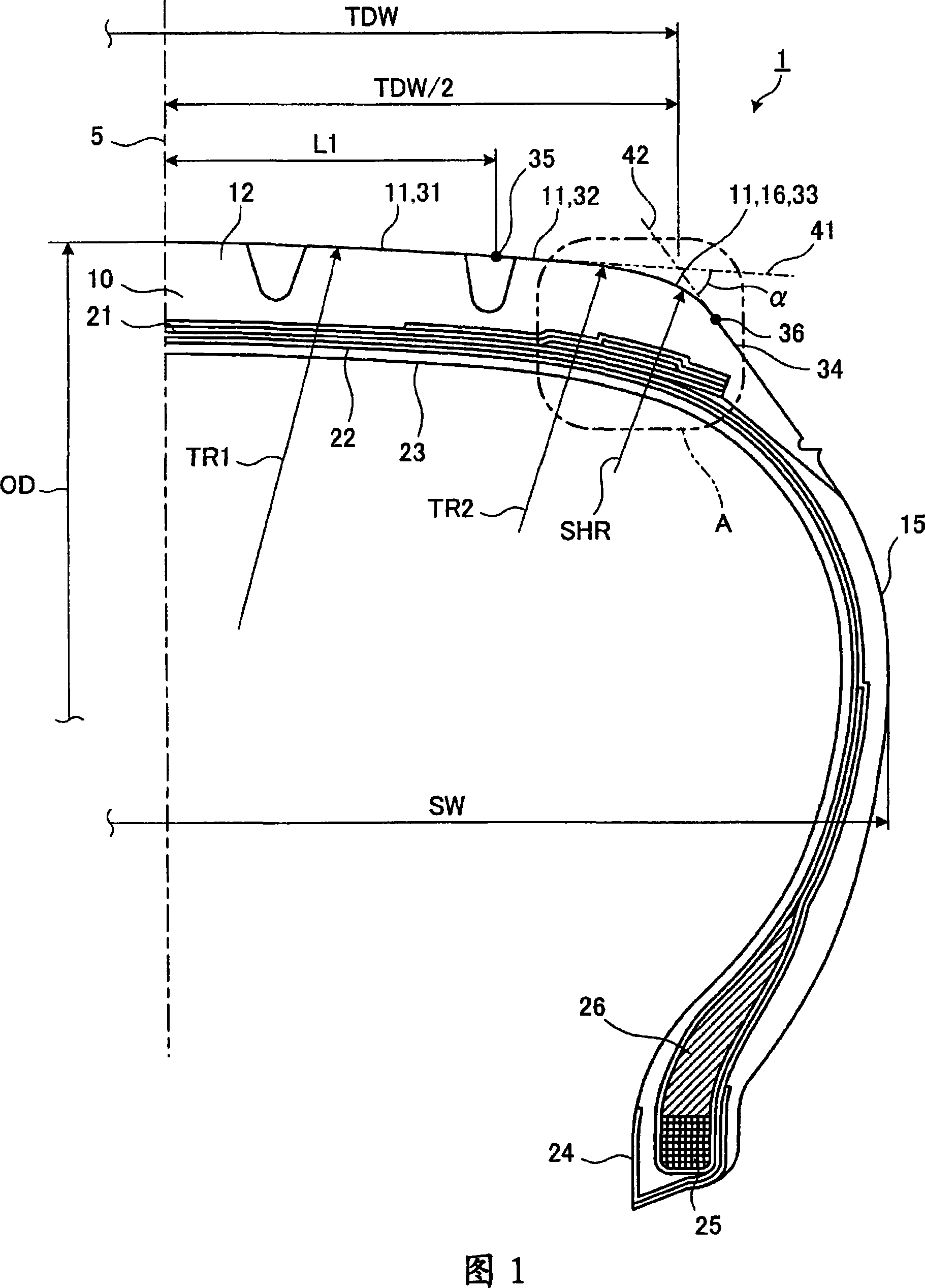
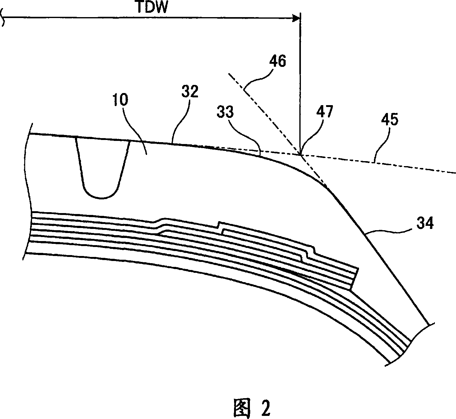
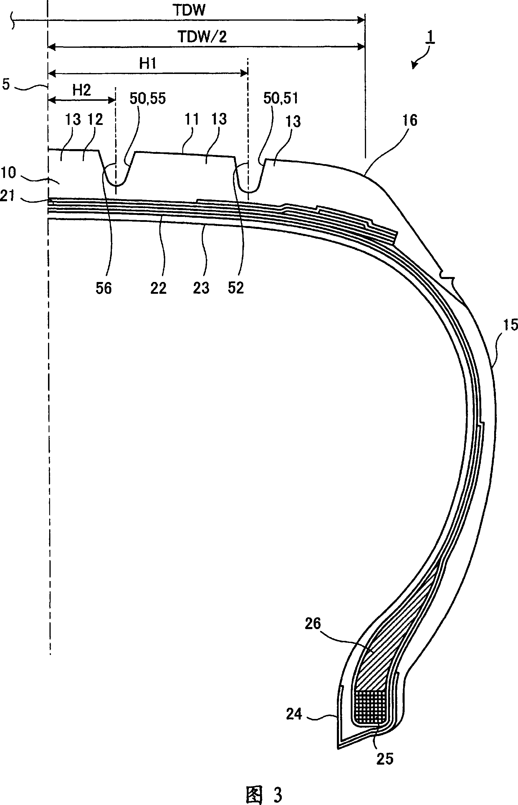
[0121] In the following description, the tire width direction refers to the direction parallel to the rotation axis of the pneumatic tire, the tire width direction inner direction refers to the direction toward the equatorial plane in the tire width direction, and the tire width direction outer direction refers to the direction in the tire width direction. in the opposite direction to the direction towards the equatorial plane. In addition, the tire radial direction refers to a direction perpendicular to the aforementioned rotary shaft, and the tire circumferential direction refers to a direction in which the aforementioned rotary shaft is turned as a center axis of rotation. Fig. 1 is a meridian cross-sectional view showing main parts of a pneumatic tire of the present invention. The pneumatic tire 1 shown in the figure is provided with a tread portion 10 at the outermost portion in the tire radial direction when viewed from a meridian cross section. In addition, a side wall...

Embodiment

[0206] Hereinafter, with regard to the aforementioned pneumatic tire 1 , performance evaluation tests performed on a conventional pneumatic tire and the pneumatic tire 1 of the present invention will be described. Seven types of performance evaluation tests were performed, of which two types of performance evaluation tests were performed only by double-track change tests, and the other five types of performance evaluation tests were performed by double-track change tests and driving real vehicles on the test field.

[0207] Among the seven performance evaluation tests, the first test method is conducted by assembling a pneumatic tire 1 of size 225 / 65R17 on a rim, and mounting the pneumatic tire 1 on an SUV vehicle with a displacement of 1800cc for test driving. . The evaluation method of the performance evaluation test is to conduct a two-lane change test (Eric test) specified in ISO3888-2 with the aforementioned vehicle, and determine the overturning characteristics by whethe...


PUM


Abstract

To provide a pneumatic tire that can improve a rollover resistance while retaining a driving stability, a tread surface 11 is formed from a center arc 31, a shoulder-side arc 32, and a shoulder arc 33. Moreover, the tread surface 11 is formed in such a manner that a value obtained from a relation K1=L1 / (TDW×0.5) satisfies 0.6‰ K1‰ 0.8, where K1 is a relation between an outline area L1 that is a width from an equatorial plane 5 to the end of the center arc 31 and a tread development width TDW, and a ratio K2 satisfies 0.9‰ K1‰ 2.0, where K2=TR1 / OD, and K2 is a ratio of a curvature radius TR1 of the center arc 31 to a tire outside diameter OD. Furthermore, the tread surface 11 is formed in such a manner that a value obtained from a relation K3=(²×TDW) / (100×SW) satisfies 0.40‰ 3‰ 0.48, where k3 is a relation between an aspect ratio ², the tread development width TDW, and a total width SW. As a result, the rollover resistance can be improved while retaining the driving stability.

Description

technical field [0001] The present invention relates to a pneumatic tire, and more particularly, to a pneumatic tire having a tread surface whose cross-sectional shape is formed by a plurality of arcs. Background technique [0002] In conventional pneumatic tires, since the usage area of ​​the tread portion is different when driving straight and on a curve, the wear condition of each part of the tread portion changes according to the driving conditions, and uneven wear may occur. For this reason, in conventional pneumatic tires, the shape of the tread portion is appropriately shaped to reduce partial wear. For example, in Patent Document 1, in order to achieve uniformity of the ground contact pressure distribution and uniformity of the ground contact length distribution when the tread portion is in contact with the ground, the shape of the crown of the tread portion is formed by three arcs with different radii of curvature. The radius of curvature of the arc and the width o...

Claims


Application Information

Patent Timeline
Patent Type & Authority Applications(China)
IPC IPC(8): B60C11/00B60C3/06B60C5/00B60C9/22B60C11/01B60C11/04B60C11/13B60C15/06
CPCB60C11/13B60C11/0083B60C11/005B60C11/01B60C11/0306B60C3/04B60C11/00B60C2011/013B60C11/0332Y02T10/86B60C11/04B60C15/06
Inventor 松永太森田谦一
Owner THE YOKOHAMA RUBBER CO LTD
Why Eureka
Try Eureka