Lighting apparatus

A technology for lighting devices and camera devices, applied in lighting devices, lighting device parts, measuring devices, etc., can solve problems such as reduced detection accuracy, uneven brightness, and difficulty in eliminating color unevenness.

Inactive Publication Date: 2008-03-12
MORITEX CORP
View PDF0 Cites 5 Cited by
  • Summary
  • Abstract
  • Description
  • Claims
  • Application Information

AI Technical Summary

Problems solved by technology

[0009] However, even if the LEDs of RGB colors are arranged without gaps, they have to be arranged with gaps of the diameter of the element, so there is a problem that the color lights cannot be mixed sufficiently, and color unevenness occurs.
In addition, when irradiating single-color illumination light, there is a gap of 3 gaps between LEDs of the same color, which causes uneven brightness, and since the number of elements of each color is 1 / 3, the brightness can be obtained by simple calculation. Also reduced to 1 / 3 of the problem
[0010] Therefore, such color unevenness and brightness unevenness cause reflections in the case of metal products, resin products, etc. that have undergone surface gloss treatment, and if product inspection is performed based on such images, the higher the accuracy of image analysis, the more accurate the image will be. A good product is detected as a bad product, and as a result, there is a contradiction that the detection accuracy decreases
[0011] In this regard, if a color LED with RGB chips arranged in each element is used, although the color unevenness caused by the arrangement gap will not appear, it is easy to cause the light emission characteristics (color tone, brightness) of each chip to be different. Color unevenness, since it is not yet possible to disassemble colored LEDs to exchange chips, it is difficult to eliminate such color unevenness
[0012] In addition, since a light-scattering treatment agent or the like is used to uniformly mix colors of light, there is a problem that the brightness further decreases.
[0013] Furthermore, in the case of monochromatic lighting, high-brightness LEDs have to be used in order to irradiate high-brightness light, and since the brightness depends on the optical characteristics of each element of the LED used, it cannot emit light with higher brightness.

Method used


Image

  • Lighting apparatus
  • Lighting apparatus
  • Lighting apparatus

Examples


Embodiment 1

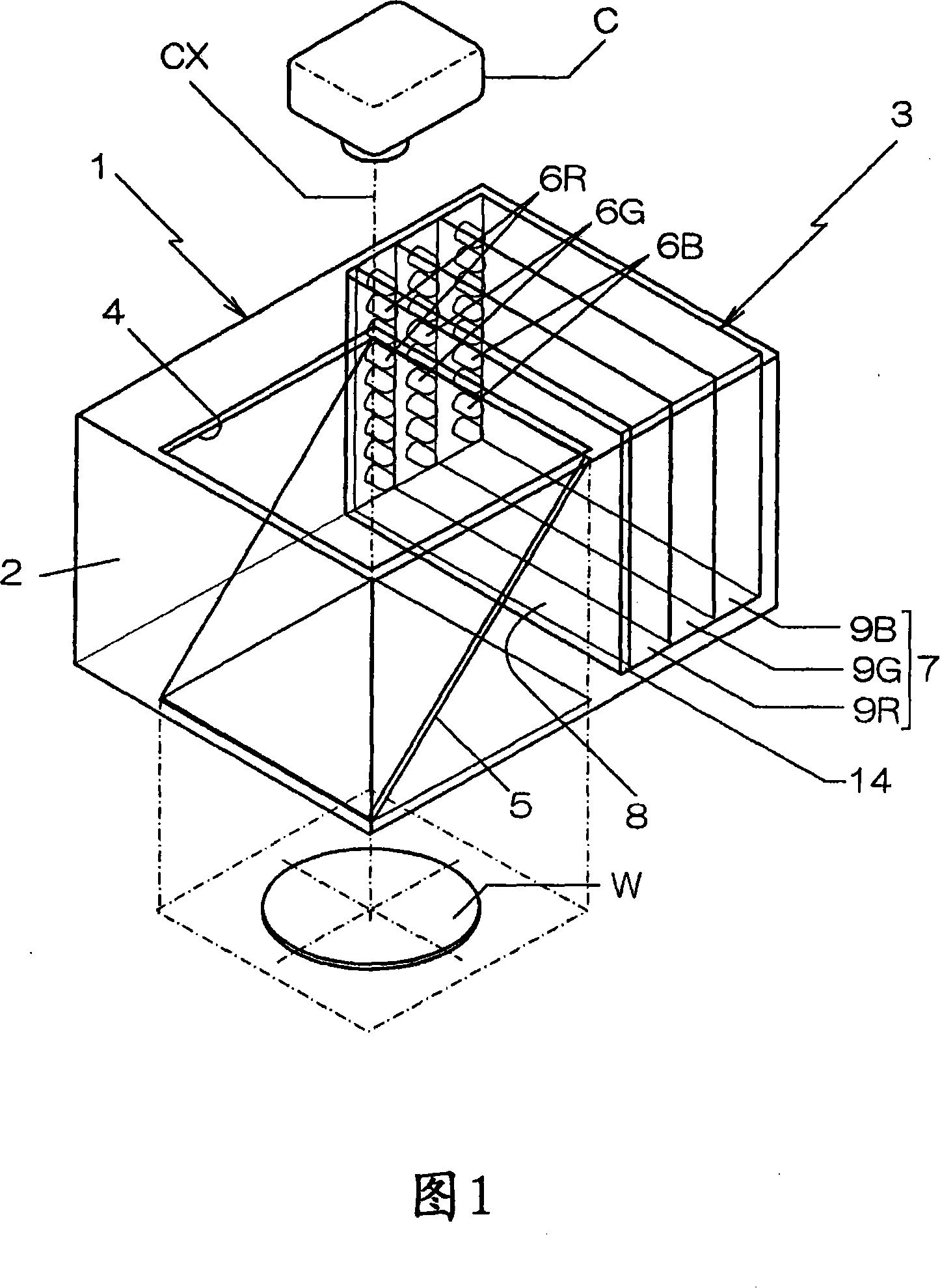
[0032] The illuminating device 1 shown in FIGS. 1 to 4 is arranged on the imaging optical axis CX from the imaging device C toward the subject W, and is used when illuminating the subject W with illumination light.

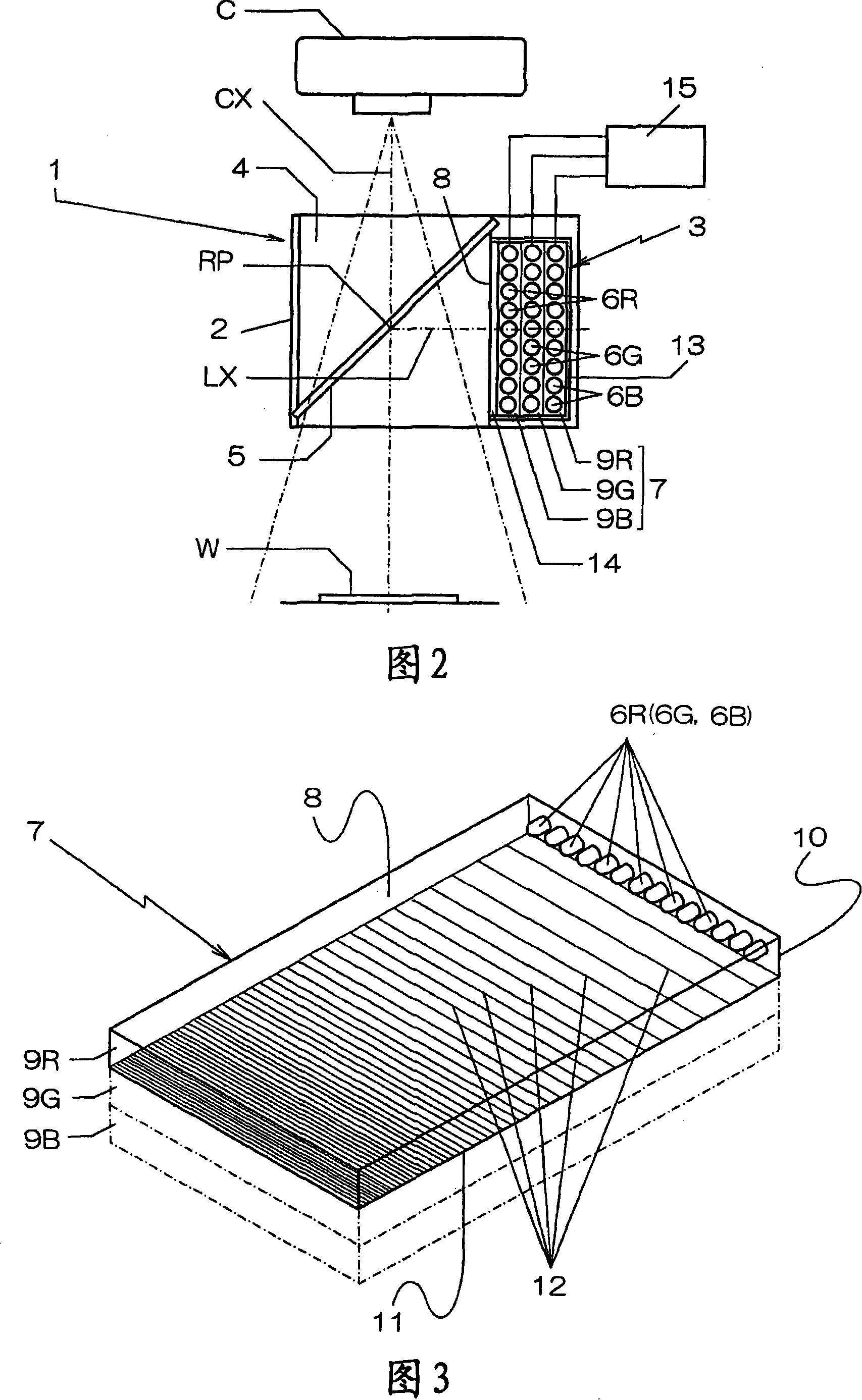
[0033] An LED light source device 3 is mounted on a cuboid body 2 to form the illuminating device 1 , and an imaging light-transmitting portion 4 through which an imaging optical axis X passes is formed on the body 2 .

[0034] Moreover, in the imaging light-transmitting part 4, the illumination optical axis LX and the imaging optical axis CX of the LED light source device 3 are intersected at a predetermined angle (in this example, a right angle), and the illumination light of the LED light source device 3 is arranged so that the illumination light of the LED light source device 3 is directed toward the object to be photographed. W reflects a half mirror (beam splitter) 5 so as to pass through this intersection point RP.

[0035] In addition, the LED light source...

Embodiment 2

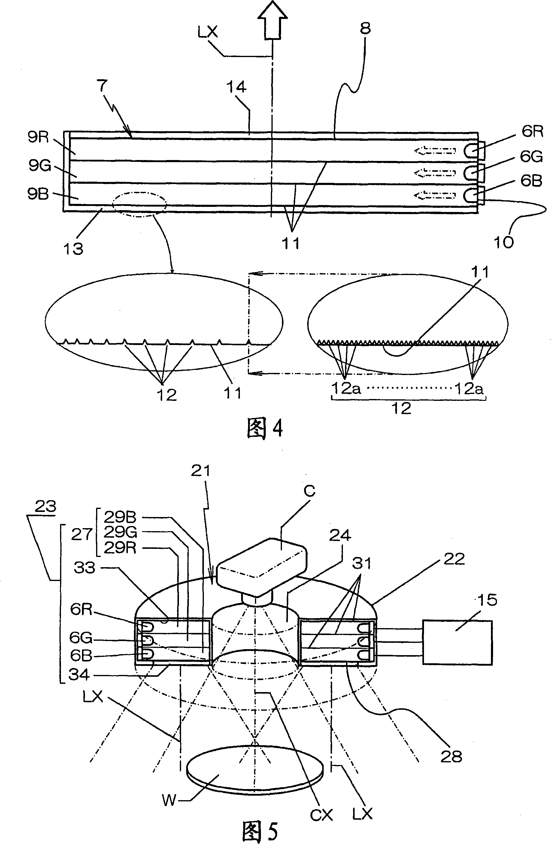
[0057] 5 and 6 show other embodiments of the lighting device of the present invention. In addition, the same code|symbol is attached|subjected to the part overlapping with FIGS. 1-4, and detailed description is abbreviate|omitted.

[0058] The body 22 of the illuminating device 21 of this example is formed into a ring that surrounds the imaging optical axis CX from the imaging device C to the subject W, and an LED light source device 23 is disposed on one side of the bottom surface thereof. 23 , so that illuminating light is irradiated from the bottom side of the body 22 , and the central part of the body 22 becomes the light-transmitting portion 24 for imaging.

[0059] This LED light source device 23 is diffused by the light guide body 27 from a variety of (in this example, RGB three primary colors) LED6R, 6G, and 6B irradiated light with different emission wavelengths. The direction of the illumination optical axis LX of the shooting object W irradiates its scattered light...

Embodiment 3

[0082] Furthermore, the body 22 or the light guide body 27 of the illuminating device 21 is not limited to a circular shape, and may be any annular polygon such as a circular triangle, a circular quadrangle, a circular hexagon, or a circular octagon, or may be a shape surrounding the imaging optical axis CX. Open circular ring or circular polygon formed by bending or bending like that.

[0083] For example, the body 42 of the illuminating device 41 shown in FIGS. The bottom side of the body 42 is irradiated with illumination light, and the central portion of the body becomes a light-transmitting portion for imaging.

[0084] This LED light source device 43 uses a light guide body 47 to scatter the light irradiated from various types of LEDs 6R, 6G, and 6B having different light emission wavelengths, and irradiates them along the direction of the illumination optical axis LX from the downward light emission surface 48 to the subject W. Scattered light.

[0085] In addition, a...


PUM


Abstract

In a lighting apparatus for conducting product inspection by irradiation of LED light at an improved inspection accuracy, an LED light source device for scattering lights of a plurality types of LEDs of different emission wavelengths by a light guiding member and irradiating them from a light emitting surface in the direction of the lighting optical axis is attached to a casing having a light transmitting imaging section through which an imaging optical axis extends, the light guiding member has a plurality of light guiding plates with the light emitting surface being directed to the lighting optical axis, each of the light guiding plates is mounted with LEDs at a predetermined pitch on the plane perpendicular to the light emitting surface, such that the combination of the emission wavelengths is identical for each of the rows in the direction of the lighting optical axis.

Description

technical field [0001] The present invention relates to an illumination device that scatters light irradiated from LEDs (light emitting diodes) of various colors inside a light guide, uniformly emits the scattered light from a light emitting surface, and irradiates an object to be photographed by an imaging device. Background technique [0002] The image inspection method is widely used in the inspection and quality control of industrial products. In order to clearly photograph products in factories, lighting devices that can continuously irradiate stable illumination light for a long period of time and consume less power are required. [0003] Therefore, there has been proposed a lighting device in which LEDs are arranged on the side of a transparent light guide whose front side serves as a light emitting surface, and the irradiation light from each LED is scattered inside the light guide to emit from the light emitting surface. [0004] [Patent Document 1] Patent No. 31872...

Claims


Application Information

Patent Timeline
Patent Type & Authority Applications(China)
IPC IPC(8): F21V8/00F21V9/08F21V19/00G03B15/02H04N5/225F21S2/00F21Y101/02G02B6/00
CPCG02B6/0081G01N21/8806G02B6/0073G02B6/0038G02B6/0068G02B6/0061G02B6/0021G02B6/0076
Inventor 吉田均清水雅之楠原大志
Owner MORITEX CORP
Why Eureka
Try Eureka