[0032] In order to further explain the technical means and effects of the present invention to achieve the intended purpose of the invention, the specific implementation, structure, and structure of the maglev shock-proof mechanism and hard disk module proposed in accordance with the present invention will be given in conjunction with the accompanying drawings and preferred embodiments. The characteristics and effects are described in detail later.
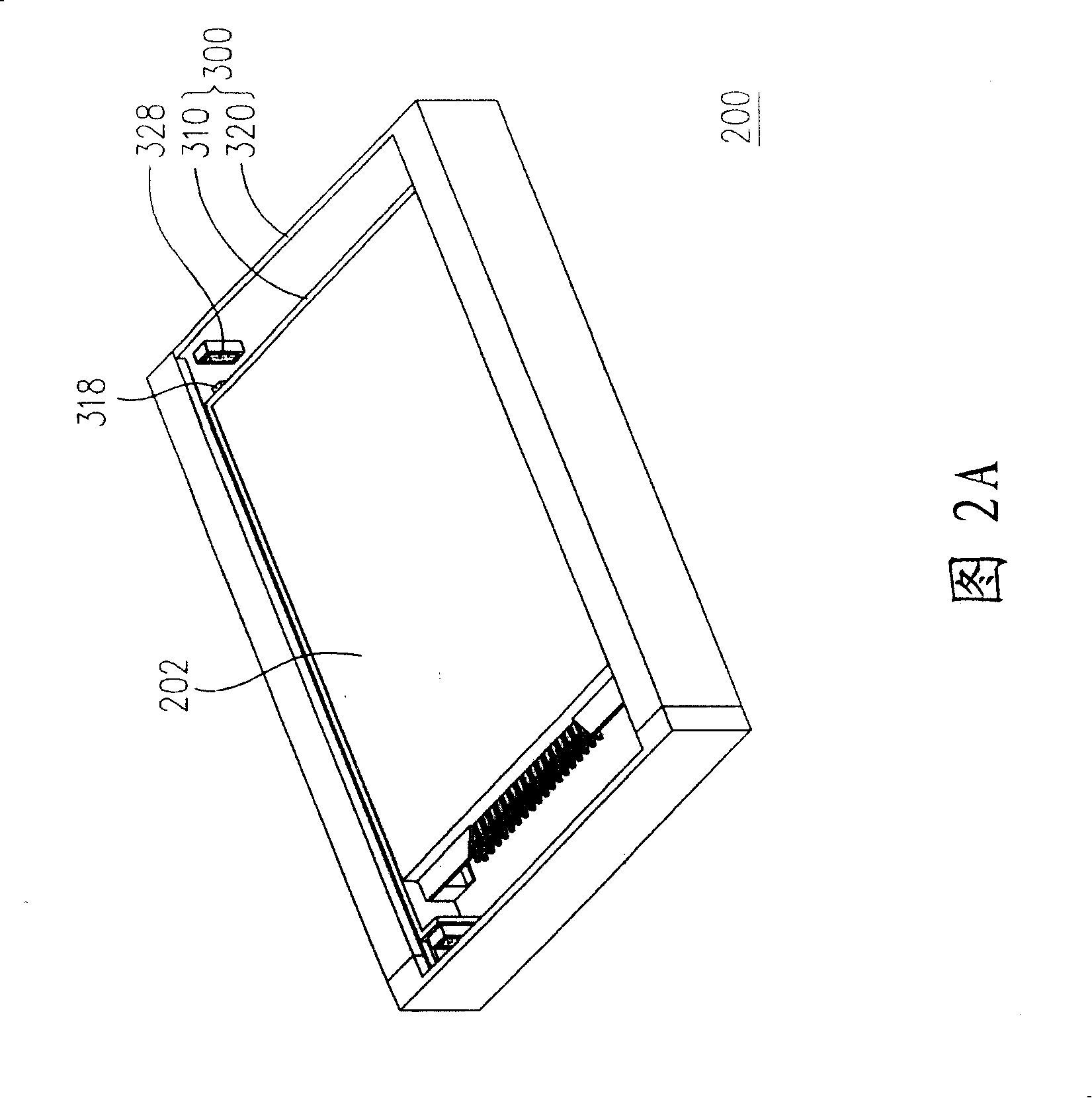
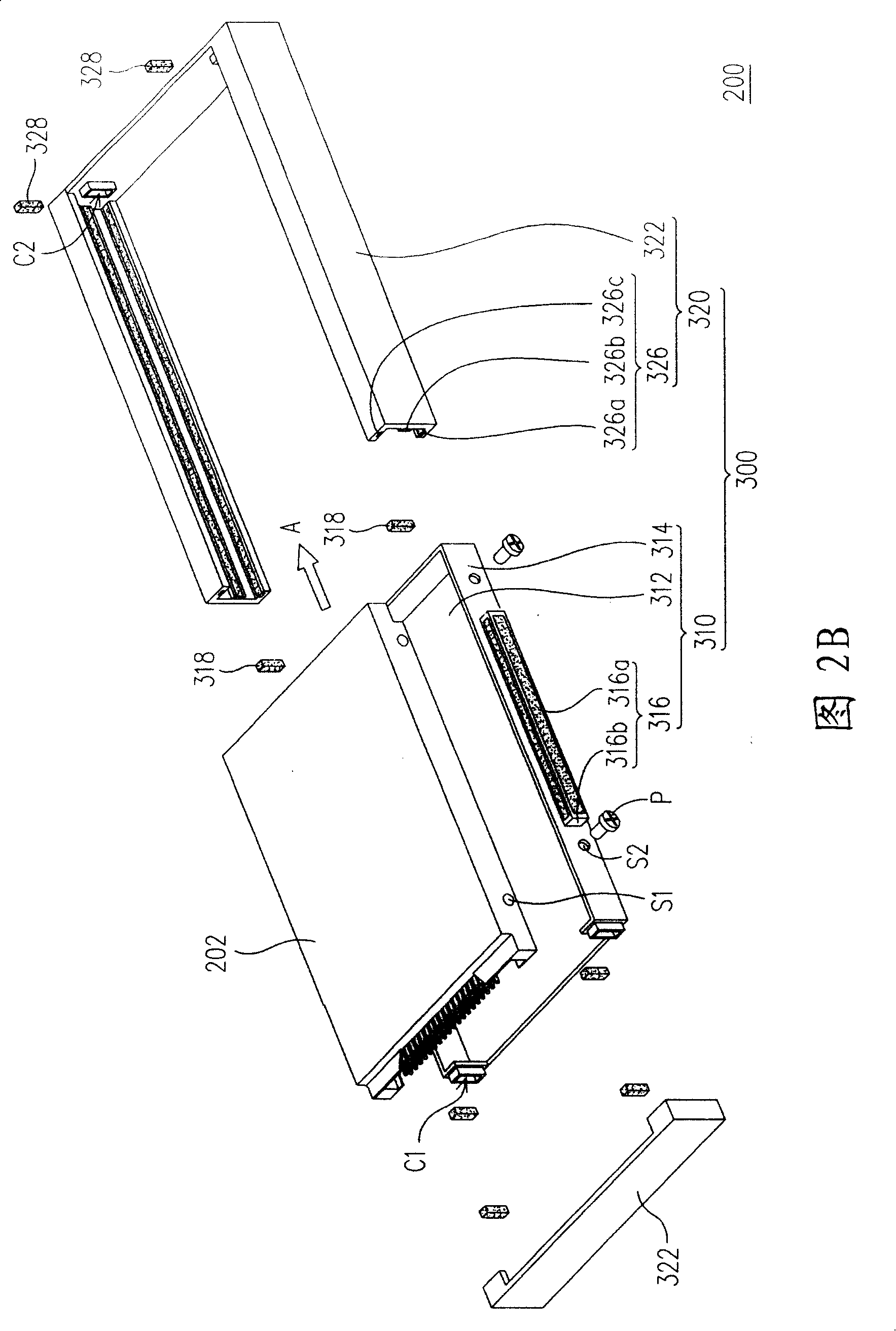
[0033] 2A is a schematic diagram of the hard disk module of the present invention, and FIG. 2B is an exploded view of the hard disk module of the present invention. 2A and 2B at the same time, the hard disk module 200 of the present invention includes a hard disk 202 and a magnetic shockproof mechanism 300. The hard disk 202 is suitable for being assembled into the maglev anti-vibration mechanism 300 to protect the hard disk 202 from damage caused by external impact. The magnetic suspension anti-vibration mechanism 300 of the present invention includes a carrier plate 310 and an outer frame 320. The carrying tray 310 is suitable for carrying the hard disk 202 and can be assembled into the outer frame 320 along the assembly direction A.
[0034] In detail, the carrier plate 310 includes a bottom plate 312, a plurality of sidewalls 314 and a plurality of first magnetic track groups 316. Wherein, the side walls 314 are disposed on the edges of the bottom plate 312 and connected to each other. It can be seen from FIG. 2B that the number of side walls 314 can be three. It should be noted here that the bottom plate 312 and the side walls 314 may be an integrally formed structure. This is only an example for illustration, and the number of the side walls 314 is not intentionally limited. In addition, the first magnetic track group 316 is disposed on two opposite sidewalls 314 outside the carrier plate 310. In order to effectively prevent the magnetic force generated by the first magnetic track group 316 from affecting the operation of the hard disk 202, the material of the bottom plate 312 and the side wall 314 can be an insulating material.
[0035] Fig. 3 is a partial enlarged schematic diagram of the first magnetic track group of the present invention. 3, in practice, the first magnetic track group 316 may include a plurality of first magnetic strips 316a and a first positioning member 316b. Wherein, the first positioning member 316b is disposed on two opposite side walls 314 outside the carrier plate 310, and the first positioning member 316b has a plurality of grooves T1, T2, and T3. In particular, the openings of the trenches T1, T2, and T3 face the first, second, and third directions, respectively, such as upward, downward, and lateral directions. Of course, the first positioning member 316b and the side wall 314 can also be integrally formed, which is not intentionally limited here. The above-mentioned first magnetic strip 316a can be positioned in the first positioning member 316b by the grooves T1, T2, and T3, respectively. It should be noted here that the number of first magnetic strips 316a only needs to correspond to the number of grooves T1, T2, and T3, but the number of the two is not deliberately limited.
[0036] On the other hand, in order to enable the hard disk 202 to be stably disposed in the carrier plate 310, the hard disk 202 and the carrier plate 310 may respectively form corresponding screw holes S1 and S2. The hard disk 202 and the carrier plate 310 can be fastened together by a plurality of bolts P. Of course, those skilled in the art can also assemble the hard disk 202 and the carrier plate 310 by snapping together, or combine the hard disk 202 and the carrier plate 310 with an adhesive. Here is not deliberately limited.
[0037] Please continue to refer to FIG. 2B, the outer frame 320 includes a plurality of side plates 322 and a plurality of second magnetic track groups 326. The number of the side plates 322 is, for example, four and they are connected to each other, and the second magnetic track group 326 is disposed on the two opposite side plates 322 in the outer frame 320. In practice, the second magnetic track group 326 may include a plurality of second magnetic stripes 326a, 326b, and 326c, and the second magnetic stripes 326a, 326b, and 326c are disposed on the side plate 322 in the outer frame 320. Fig. 4 is a partial enlarged schematic view of the outer frame of the present invention. Referring to FIG. 4, the side plate 322 in the outer frame 320 can form a plurality of grooves G1, G2, and G3 corresponding to the number of the second magnetic strips 326a, 326b, and 326c. The second magnetic track group 326 can be fixed on the side plate 322 in the outer frame 320 through the grooves G1, G2, and G3.
[0038] It is worth noting that after the carrier plate 310 and the outer frame 320 are assembled, the first magnetic track group 316 and the second magnetic track group 326 will correspond to each other, and the two corresponding first magnetic track group 316 and the second magnetic track group 326 can be mutually exclusive by magnetic force. In detail, the first magnetic stripe 316a located in the trenches T1 and T3 can be mutually exclusive with the second magnetic stripe 326a, 326c located in the trenches G1 and G3, respectively. In other words, the first magnetic strip 316a and the second magnetic strip 326a, 326c located in the trenches T1 and T3 can effectively buffer the impact force in the vertical direction.
[0039]On the other hand, the first magnetic strip 316a and the second magnetic strip 326b located in the trench T2 can be mutually exclusive, so as to effectively buffer the impact force in the horizontal direction. In this way, the carrier plate 310 and the outer frame 320 can form a buffer space through the mutually repulsive magnetic force between the first magnetic track group 316 and the second magnetic track group 326, thereby effectively avoiding the carrier plate 310 and the outer frame 320 Collide with each other. In this way, the hard disk 202 on the carrier plate 310 can be effectively protected, thereby prolonging the service life. Of course, the first magnetic track group 316 and the second magnetic track group 326 can also be magnetic tracks of other numbers and shapes, as long as the mutually repulsive magnetic force between the first magnetic track group 316 and the second magnetic track group 326 can make the carrier disk 310 and the outer frame 320 only need to maintain a buffer space, which is not intended to be limited here.
[0040] Please continue to refer to FIG. 2B. In order to further improve the shockproof effect of the hard disk 202, the magnetic suspension shockproof mechanism 300 of the present invention further includes a plurality of first magnets 318 and a plurality of second magnets 328. The first magnet 318 is disposed on the side wall 314 outside the carrier plate 310, and the second magnet 328 is disposed on the side plate 322 in the outer frame 320. It should be noted that the first magnets 318 can respectively correspond to the second magnets 328 and mutually repel each other by magnetic force. In practice, the arrangement direction of the two corresponding first magnets 318 and second magnets 328 may be along the extending direction of the first magnetic track group 316. Specifically, the mutually repulsive magnetic force between the first magnet 318 and the second magnet 328 can effectively protect the hard disk 202 to buffer the impact force parallel to the direction of the first magnetic track group 316.
[0041] In practice, in order to enable the first magnet 318 and the second magnet 328 to be respectively fixed on the side wall 314 of the carrier plate 310 and the side plate 322 of the outer frame 320, the side wall 314 and the side plate 322 can be respectively formed with grooves C1 and C2. The first magnet 318 can be fixed on the side wall 314 of the carrier plate 310 by the groove C1, and the second magnet 328 can be fixed on the side plate 322 of the outer frame 320 by the groove C2. Of course, those skilled in the art can also fix the first magnet 318 on the side wall 314 of the carrier plate 310 through an adhesive and fix the second magnet 328 on the side plate 322 of the outer frame 320. This is only an example, and is not intentionally limited.
[0042] In summary, since the carrier plate and the outer frame of the present invention are respectively provided with the first magnetic track group and the second magnetic track group that repel each other, a buffer space can be formed between the carrier plate and the outer frame to effectively avoid carrying The disc and the outer frame collide with each other. Therefore, the hard disk module of the present invention can effectively reduce the impact of external force in different directions by the action of the first magnetic track group and the second magnetic track group, thereby achieving the purpose of protecting the hard disk and prolonging the service life.
[0043] The above are only the preferred embodiments of the present invention, and are not intended to limit the present invention in any form. Although the present invention has been disclosed as above in preferred embodiments, it is not intended to limit the present invention. Anyone familiar with the profession Those skilled in the art, without departing from the scope of the technical solution of the present invention, can make use of the technical content disclosed above to make slight changes or modifications into equivalent embodiments with equivalent changes, provided that the technical content of the present invention is not deviated from the technical solution of the present invention. Technical essence Any simple modification, equivalent change and modification made to the above embodiments still belong to the scope of the technical solution of the present invention.