
Implant for placing in a blood circulation conduit

一种导管、循环通道的技术,应用在植入物领域,能够解决闸门损坏、不能可靠工作等问题

Inactive Publication Date: 2012-06-06
CORMOVE
View PDF0 Cites 0 Cited by
  • Summary
  • Abstract
  • Description
  • Claims
  • Application Information

AI Technical Summary

Problems solved by technology

However, the gate and its blades cannot work reliably and satisfactorily for a long time after partial deformation.
As a result the gate will soon fail and the inner valve must be replaced

Method used


Image

  • Implant for placing in a blood circulation conduit
  • Implant for placing in a blood circulation conduit
  • Implant for placing in a blood circulation conduit

Examples


Embodiment Construction

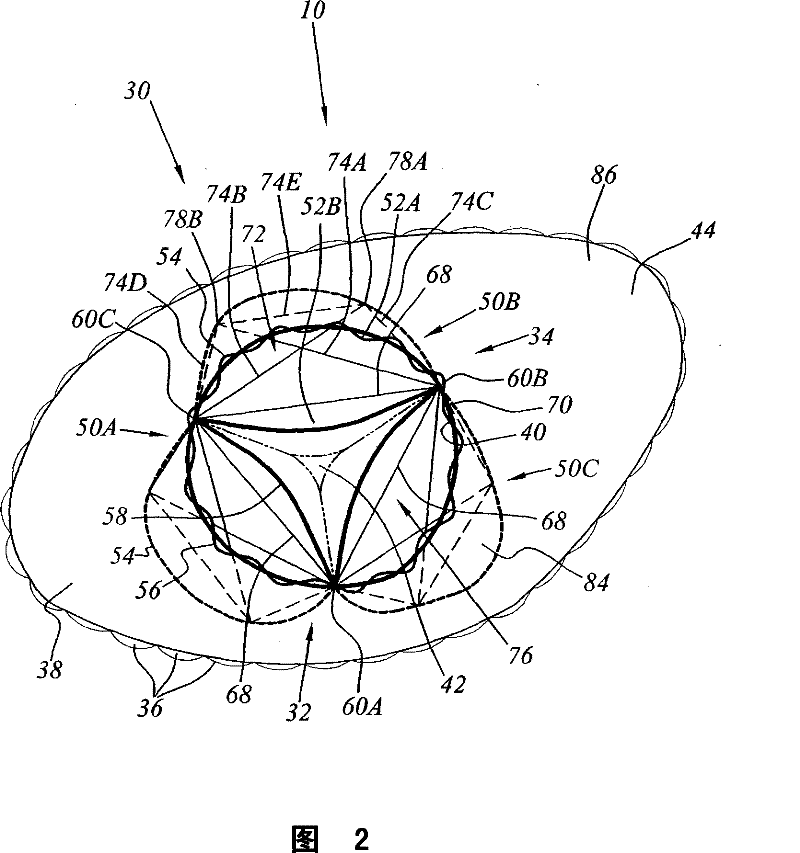
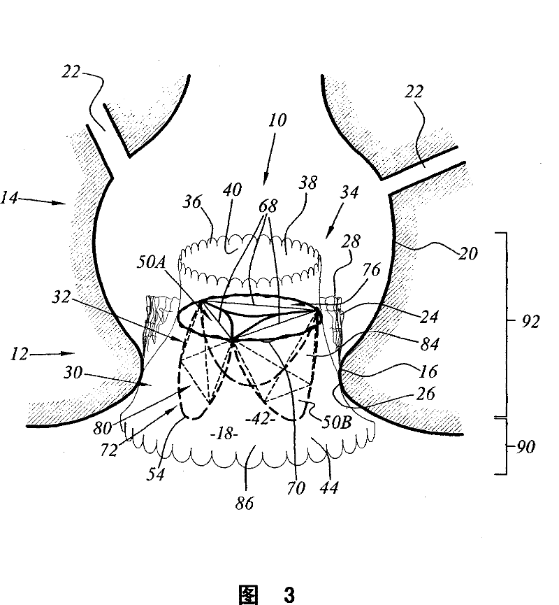
[0029] Figure 1 to Figure 4 A first implantable inner valve 10 according to the present invention is illustrated. Such as image 3 As shown, the implantable internal valve 10 is an internal valve for replacing a defective native valve 12 in a coronary sinus 14 .

[0030] The coronary sinus 14 is surrounded by a wall having a narrowed portion 16 defining a blood circulation opening 18 and an enlarged region 20 on which two coronary arteries 22 open. The narrowed portion 16 forms the base of the native valve 12 .

[0031] Native valve 12 includes leaflet 24 having a lower edge 26 that engages narrow portion 16 and a free upper edge 28 that protrudes into coronary sinus 14 opposite dilated wall 20 .

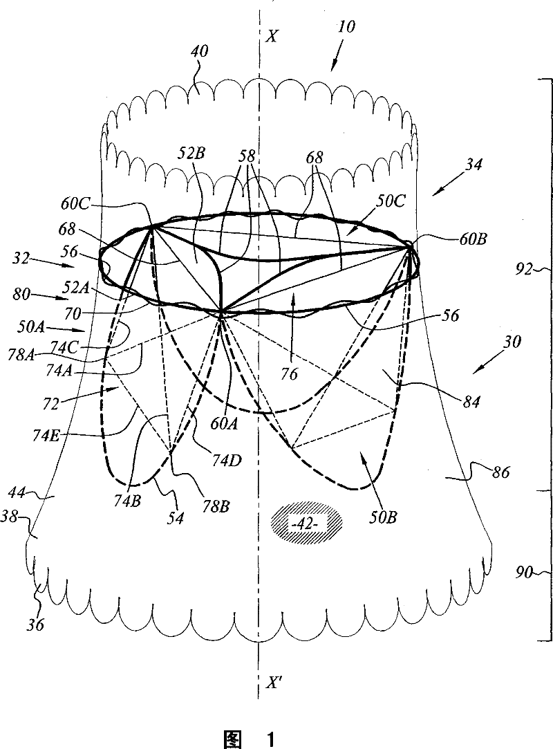
[0032] see figure 1 The implantable internal valve 10 includes a radially expandable strut endoprosthesis 30 and an elastic gate 32 permanently fixed within the endoprosthesis 30 .

[0033] According to the invention, the implantable endovalve 10 also comprises a unit 34 for c...


PUM


Abstract

The implant ( 10 ) of the present invention comprises a hollow body ( 30 ) adapted to be deployed between a compressed configuration and a totally dilated configuration constituting its rest configuration. The hollow body ( 30 ) has an internal surface ( 40 ) with an axis (X-X') which delimits a blood circulation passage ( 42 ). The implant ( 10 ) comprises at least a constricting flexible threadlike link ( 68 ) which is linked to the hollow body at at least two linking points ( 60A, 60B, 60C) which are spaced angularly round the axis (X-X') on its internal surface ( 40 ). The link ( 68 ) canbe deployed between a retracted state and a deployed state during deployment of the hollow body ( 30 ). The distance separating the linking points ( 60A, 60B, 60C) in the deployed state of the threadlike link ( 68 ) is smaller than the distance separating these points ( 60A, 60B, 60C) in the totally dilated configuration of the hollow body ( 30 ) in the absence of threadlike link ( 68 ).

Description

technical field [0001] The present invention relates to implants for implantation in blood circulation conduits, such implants comprising a hollow body which can be expanded from a compressed configuration to a fully expanded configuration which constitutes its Resting configuration, said hollow body has an inner surface with axis XX' forming a blood circulation channel. [0002] The invention may be particularly applicable to internal valves formed from elastic obturateurs, fitted in tubular endoprostheses and used to replace natural heart valves. Background technique [0003] The heart has a valve at the outlet of the right ventricle (pulmonary valve) and a valve at the outlet of the left ventricle (aortic valve). [0004] However, there are some diseases that can affect the valve. In particular, the valves can undergo calcification allowing blood to flow back, or regurgitate, back into the ventricle from which it was just expelled. Reflux problems lead to abnormal dila...

Claims


Application Information

Patent Timeline
Patent Type & Authority Patents(China)
IPC IPC(8): A61F2/24A61F2/06A61F2/94
CPCA61F2230/0067A61F2/2418
Inventor M·斯帝瑞克E·贝鲁斯
Owner CORMOVE
Learn More