Minisize drill bit for PCB plate drilling hole

A micro-drill and PCB board technology, applied in drilling/drilling equipment, boring machine/drilling machine components, drill repairing, etc., can solve the problems of insufficient chip removal ability, affecting rigidity, small helix angle, etc., to improve the hole wall The effect of quality, improved dust removal capacity, and large chip removal space

Active Publication Date: 2011-11-16
SHENZHEN JINZHOU PRECISION TECH
View PDF0 Cites 0 Cited by
  • Summary
  • Abstract
  • Description
  • Claims
  • Application Information

AI Technical Summary

Problems solved by technology

[0007] 1. The groove type is not good enough, such as figure 1 As shown, the groove of the ordinary micro-drill bit is close to semicircle when viewed from the vertical helix section, but viewed from the end face, the transition from the cutting edge to the grinding back is very smooth (such as image 3 As shown), for this kind of groove, the groove width will inevitably lead to the deep groove, and conversely, the shallow groove will inevitably lead to the narrow groove, which cannot improve the rigidity while improving the quality of the drilled hole wall. Contradictions and mutual constraints lead to the inability to simultaneously improve the drilling wall quality, hole position accuracy, and drill breaking performance of micro-drills, and it is difficult to improve the overall performance.
[0008] 2. The helix angle is small and the chip removal capacity is not enough, especially in the occasions where the number of drilling layers is relatively high and the dust removal is difficult, the quality of the hole wall cannot meet the requirements well
[0009] 3. The taper of the core diameter remains unchanged, and the distribution of the strength beams of the micro-drill is uneven, which affects the rigidity

Method used


Image

  • Minisize drill bit for PCB plate drilling hole
  • Minisize drill bit for PCB plate drilling hole
  • Minisize drill bit for PCB plate drilling hole

Examples


Embodiment Construction

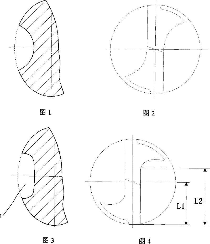
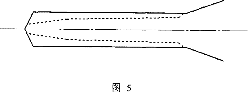
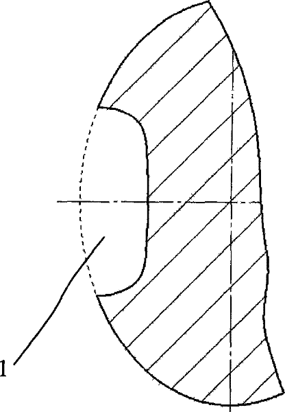
[0026] Such as Figure 3 to Figure 5 As shown, the present invention provides a micro-drill used for drilling holes in PCB boards, the cylindrical surface of which is provided with a spirally rising groove 1 . The main difference between the present invention and existing miniature drill bit is:

[0027] 1. The groove is optimized, and the cross section of the groove perpendicular to the helix is ​​designed as a discontinuous arc, such as image 3 In the illustrated embodiment, viewed from the cross section perpendicular to the helix, the cross-sectional profile of the groove 1 is generally U-shaped with a wide bottom, including the bottom line at the bottom of the groove and two lines on both sides of the groove. The side line that smoothly connects with the bottom line, wherein the bottom line is a straight line segment or an arc line segment with a large radius of curvature, and when the arc line segment with a large radius of curvature is used, the bottom line is relative...


PUM


Abstract

The invention discloses a PCB-drilling micro-bit, comprising an base line at the bottom of the groove and two side lines respectively arranged at both sides of the groove and smoothly connected with the base line, which is characterized in that: a spiral winding groove is arranged on the prismatic face; the cross-section profile vertical to the spiral line of the groove is U-shaped with wide bottom on the whole; wherein, the base line is a straight line segment or a circular arc line segment with large curvature radius; the two side lines are respectively straight line segment or circular arcline segment with small curvature radius. Optimally, Helix angle of the groove is 42 to 45 degrees. The invention has the advantages of having bigger space for removing chips and bigger core radius synchronously through optimizing the groove, not decreasing the width of the groove with the groove becoming shallower, having more reasonable groove amplitude ratio of the rear part in the drill bit, improving the quality of drill wall, the hole accuracy, lowering rod-breaking performance synchronously; by increasing the helix angle to 42 to 45 degrees, the invention improves the dust exhausting ability of the drill bit and the quality of hole wall.

Description

technical field [0001] The invention relates to a PCB board processing tool, in particular to a miniature drill bit used for drilling a PCB board. Background technique [0002] At present, in the field of micro-drills used for processing printed circuit boards, the main indicators to measure the performance of micro-drills for processing printed circuit boards include: drilling hole wall quality, hole position accuracy, drill breaking performance, and wear performance. There are many factors that determine these performances, including grooves, helix angles, and core diameter tapers. The specific effects of these three factors on the performance of micro-drills are as follows: [0003] 1. The groove affects the drill hole wall quality, hole position accuracy and drill breaking performance of the drill bit. The width of the groove determines its chip removal performance. The wider the groove, the smoother the chip removal and the higher the quality of the hole wall. Therefor...

Claims


Application Information

Patent Timeline
Patent Type & Authority Patents(China)
IPC IPC(8): B23B51/00
Inventor 屈建国邹卫贤王成勇武凤伍
Owner SHENZHEN JINZHOU PRECISION TECH
Why Eureka
Try Eureka