
Signal detection method and apparatus

A signal detection and signal technology, applied in the direction of preventing/detecting errors through diversity reception, space transmit diversity, digital transmission systems, etc. process, the effect of reducing complexity

Active Publication Date: 2011-10-26
HUAWEI TECH CO LTD +1
View PDF0 Cites 2 Cited by
  • Summary
  • Abstract
  • Description
  • Claims
  • Application Information

AI Technical Summary

Problems solved by technology

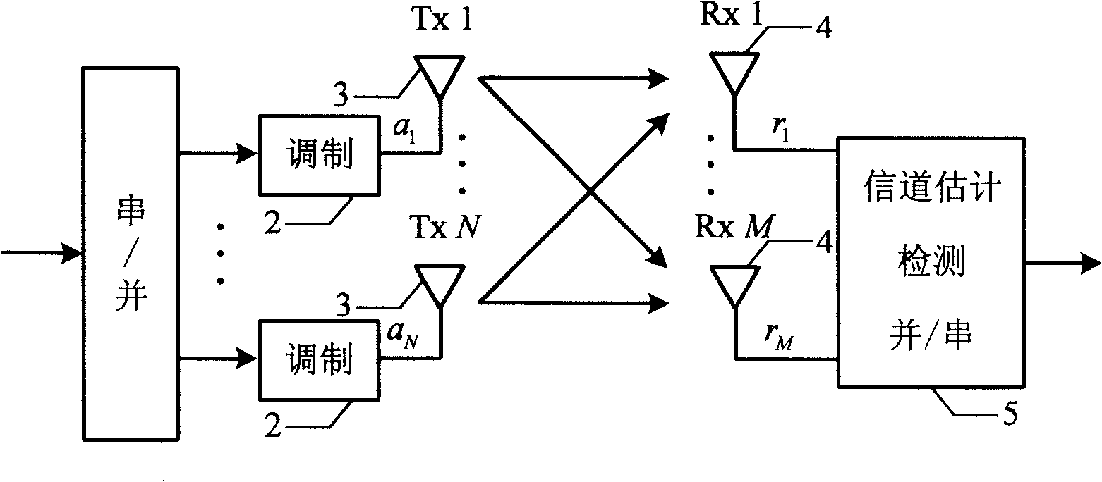
[0013] However, the weakness of this algorithm is that it is necessary to calculate a pseudo-inverse when calculating the zero-setting vector in each signal detection, and the complexity of calculating a pseudo-inverse is O(N 3 ), so the complexity of the whole algorithm is O(N 4 ), where N represents the number of transmitting antennas
In the case of a large number of transmitting antennas, the complexity of the algorithm is very high, which affects the signal detection speed

Method used


Image

  • Signal detection method and apparatus
  • Signal detection method and apparatus
  • Signal detection method and apparatus

Examples


Embodiment Construction

[0034] In order to make the purpose, technical means, and advantages of the present invention clearer, the present invention will be further described in detail below with reference to the accompanying drawings and embodiments.

[0035] Figure 4 It is an overall flowchart of a signal detection method according to an embodiment of the present invention. Such as Figure 4 As shown, the method includes:

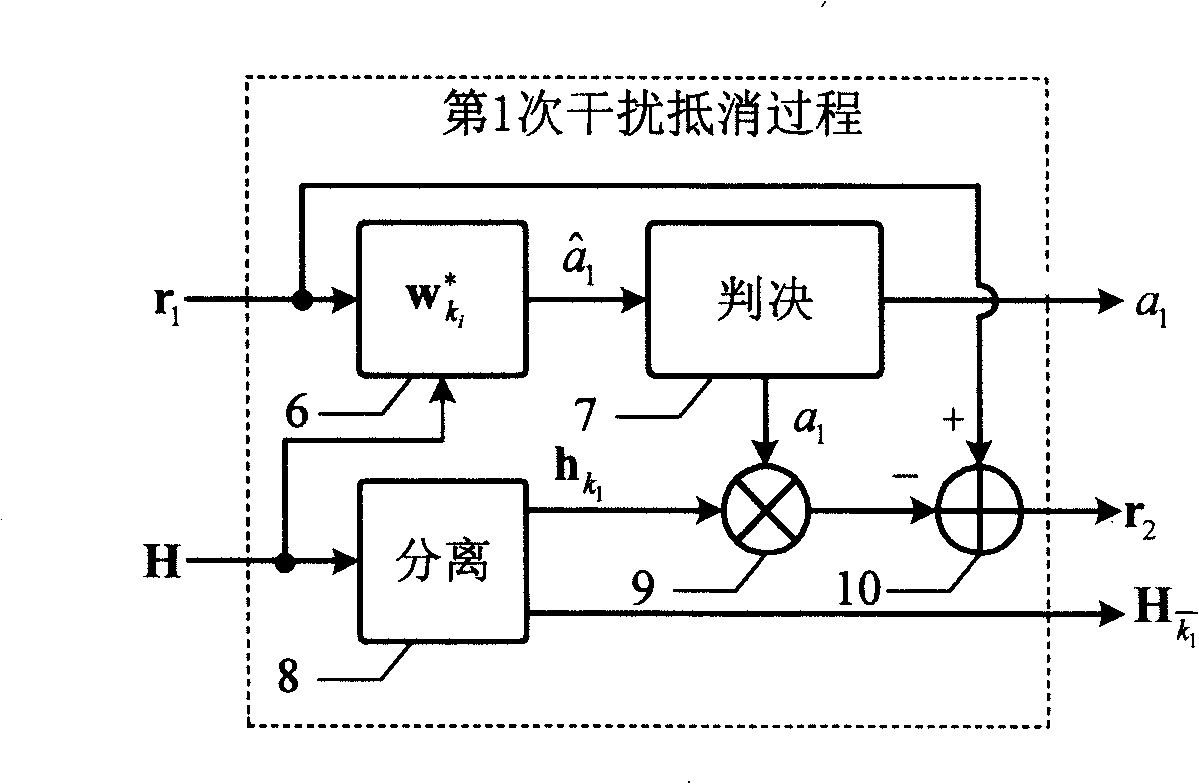
[0036] Step 401: Receive a transmission signal to form a reception signal, and obtain a zero-setting vector corresponding to the transmission signal according to the system matrix.

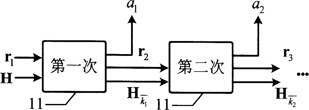
[0037] Step 402: According to the zero-setting vector corresponding to the transmission signal, the transmission signals are detected in the order of decreasing SNR after detection, and after each transmission signal is detected, the interference of the detected transmission signal in the reception signal is eliminated, And according to the zero-setting vector corresponding to the detected transmission s...


PUM


Abstract

The embodiment of the invention discloses a method for detecting signal, which includes the following steps: receiving transmitted signals, forming received signals, acquiring zero padding vectors corresponding to the transmitted signals according to the system matrix, detecting the transmitted signals in turn according to the zero padding vectors corresponding to the transmitted signals, eliminating the disturbance of the detected transmitted signals in the received signals after every transmitted signal is detected, and renovating the zero padding vectors of the undetected transmitted signals according to zero padding vectors corresponding to the detected transmitted signals for the detection of the next transmitted signal. In the embodiment of the invention, zero padding vectors corresponding to the detected transmitted signals are used for renovating the zero padding vectors of the undetected transmitted signals, so that fussy repeated pseudo-inverse process is avoided. Complexityof signal detection is greatly reduced while the original algorithm general structure needs not to be changed. The embodiment of the invention also discloses a signal detection device, which includesa receiving module, a zero padding vector module and a signal detection module.

Description

Technical field [0001] The present invention relates to the receiving technology of a multiple input multiple output (MIMO) antenna system, in particular to a signal detection method and equipment. Background technique [0002] Information theory research shows that the multipath scattering channel contains huge capacity. In an environment with rich multipath components, the MIMO system can make full use of the multipath components. Based on this, scientists have proposed a Diagonally Bell Labs Layered Space-Time Wireless Communication structure used in the MIMO system. Architecture, D-BLAST), multiple antenna structures are used in both the transmitter and the receiver, and the transmitted information is space-time coded diagonally. In an independent Rayleigh fading environment, this structure obtains a huge capacity, which increases linearly with the number of transmitting antennas, and can reach 90% of the Shannon channel capacity. But one of the drawbacks of the D-BLAST sys...

Claims


Application Information

Patent Timeline
Patent Type & Authority Patents(China)
IPC IPC(8): H04L1/00H04L1/06H04B7/08
Inventor 林华炯唐友喜刘发彪
Owner HUAWEI TECH CO LTD
Learn More