Vented disc brake rotor

A ventilated, rotor technology, applied in the direction of the brake disc, etc., can solve the problem that the designer cannot fully understand the brake whistle and so on

Inactive Publication Date: 2008-06-18
FEDERAL MOGUL CORP
View PDF0 Cites 8 Cited by
  • Summary
  • Abstract
  • Description
  • Claims
  • Application Information

AI Technical Summary

Problems solved by technology

[0008] Despite the effectiveness of the complex eigenvalue method as a diagnostic tool, designers still do not fully understand the possible mechanisms that produce brake squeal and need to continue to seek new and improved solutions to fully, or at least adequately, , to eliminate the root cause of brake squeal - harmful audible frequencies

Method used


Image

  • Vented disc brake rotor
  • Vented disc brake rotor
  • Vented disc brake rotor

Examples


Embodiment Construction

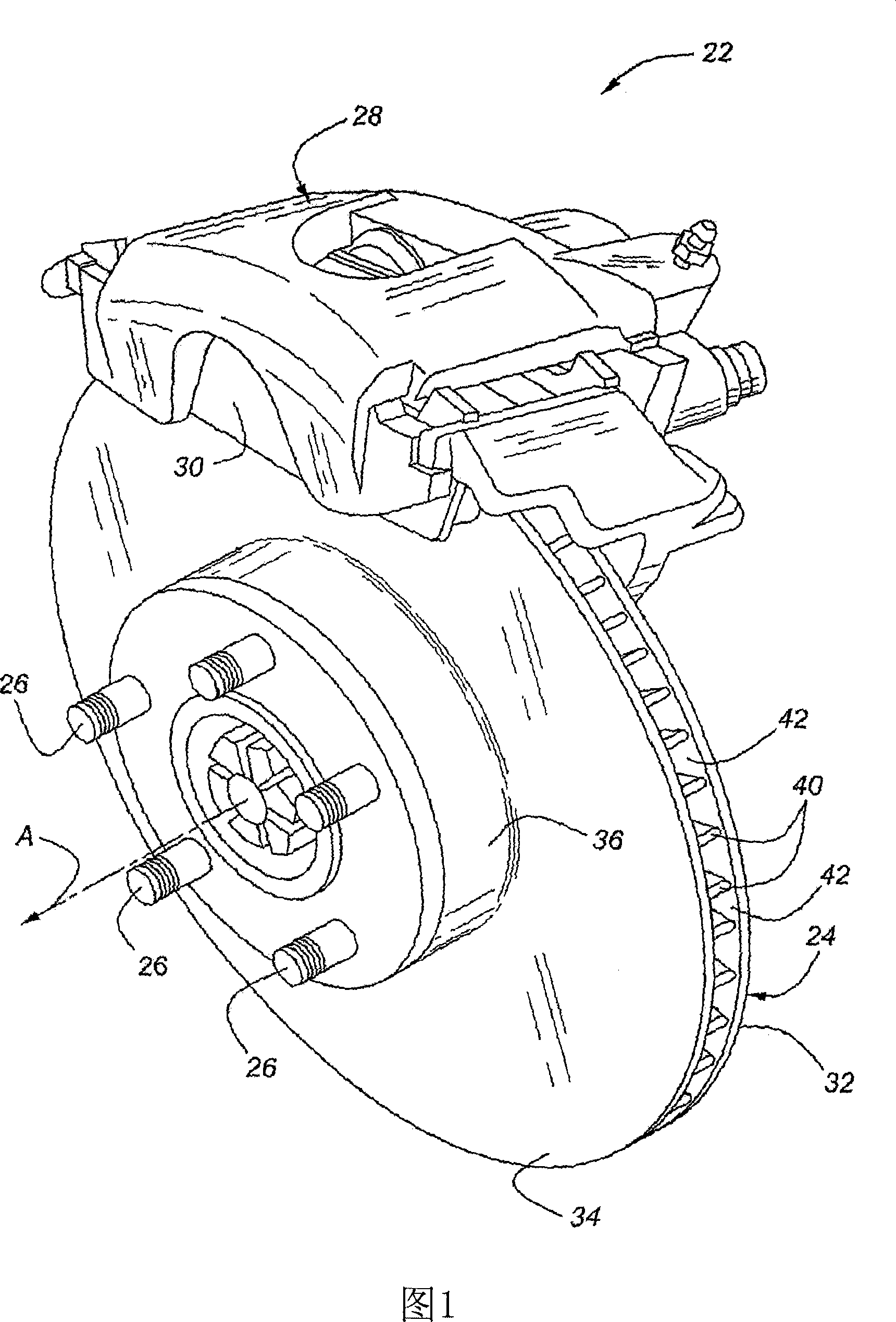
[0026] Referring to the drawings, wherein like numerals refer to like or corresponding parts throughout, a disc brake rotor assembly 22 is shown in FIG. Wheels, not shown, are attached above lug bolts 26 . Calipers 28 support a pair of brake pads 30 on opposite sides of rotor 24 . In response to hydraulic, wind, electromagnetic or other actuation initiated by the vehicle operator, disc brake pads 30 are compressed and clamped into contact with opposing friction surfaces of rotor 24 to prevent wheel rotation.

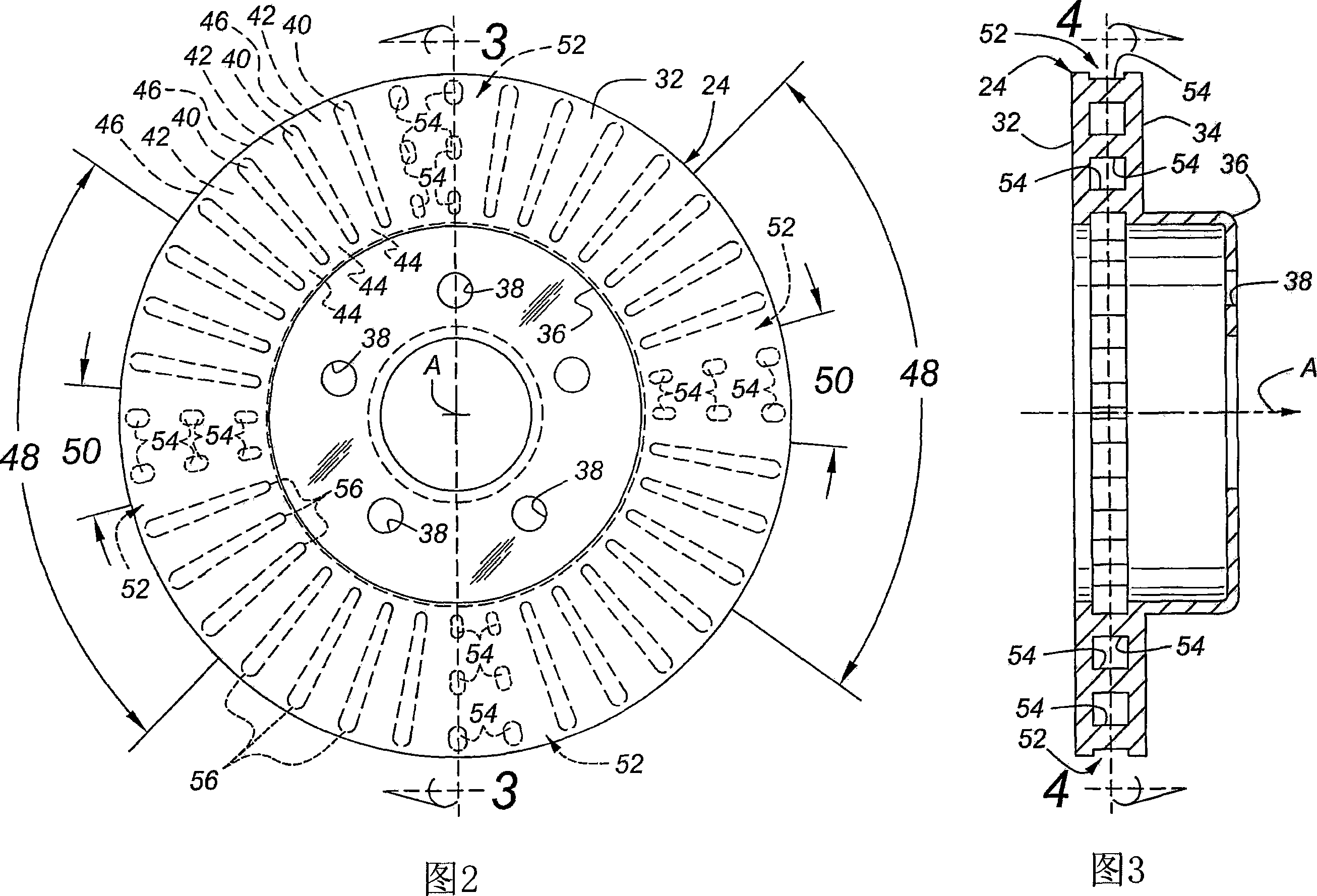
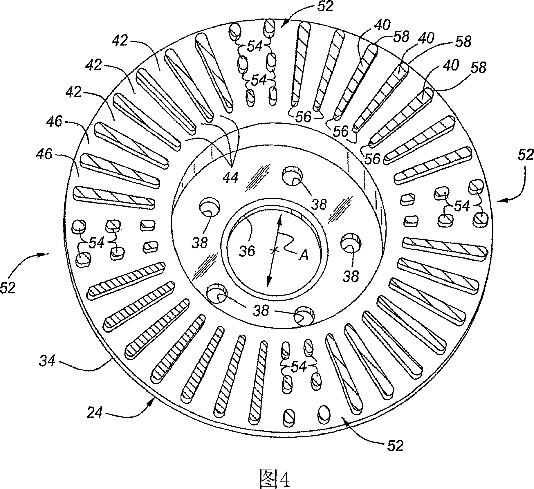
[0027] In a possibly preferred embodiment as shown in Figures 2-4 and 7A, the rotor 24 is of the ventilated type and includes an annular inner friction plate 32 centered on a central axis A. The central axis A coincides with the axis of rotation of the associated wheel. The annular outer friction plate 34 is spaced apart from the inner friction plate 32 and concentrically arranged around the central axis A. As shown in FIG. The inner edge of the outer friction plate 3...


PUM


Abstract

A brake disc assembly (22) for a vehicle includes a ventilated rotor (24) defined by vent holes (42) between inboard (32) and outboard (34) friction plates. The vent holes (42) are separated by ribs (40) spaced in regular circumferential increments about the rotor (24). The rib pattern (40) is divided into two or more sectors (48) of equal angular measure. Within each sector (48), an attenuation region (50) interrupts two or more ribs (40) by replacing the ribs (40) with a cluster of individual pins (54) which may be arranged in radial and circumferential rows. The pins (54) can have consistent circular or varying cross-sectional configurations. Each attenuation region (50) spans a territory within each sector (48) that is preferably at least 20% and less than 55% of the sector (48) real estate. The rib pattern (40) completely or at least substantially eliminates vibration modes in objectionable, audible frequencies without adversely affecting the structural integrity, cooling capabilities or functional attributes of the disc brake assembly (22).

Description

[0001] Refer to related application [0002] This application claims the benefit of U.S. Provisional Patent Application No. 60 / 666,667, filed March 30, 2005, and U.S. Patent Application No. 11 / 206,889, filed August 18, 2005, the latter being hereby incorporated as refer to. field of invention [0003] The invention relates to disc brake rotors, in particular to a ventilated rotor for weakening brake squealing noise. Background technique [0004] The rotors of disc brakes form part of the vehicle's braking system and rotate with the wheels. The rotor has two opposing friction surfaces against which the brake pads come into contact to stop the rotation of the wheel. In many occasions, the two friction surfaces of the disc brake rotor are ventilated to improve the cooling characteristics by dissipating the heat generated by friction during braking. Vented rotors are typically employed to form a plurality of radially extending ventilation holes between the inner and outer fri...

Claims


Application Information

Patent Timeline
Patent Type & Authority Applications(China)
IPC IPC(8): F16D65/12
Inventor 简·卢乔治·罗伯特·施密特
Owner FEDERAL MOGUL CORP
Why Eureka
Try Eureka