

Electrically driven truck
A technology of carts and electric rudders, which is applied in the field of electric carts, and can solve the problems of large electric carts, obstacles to electric carts, and inability to operate flexibly.
- Summary
- Abstract
- Description
- Claims
- Application Information
AI Technical Summary
Problems solved by technology
Method used
Image

Examples
Embodiment Construction
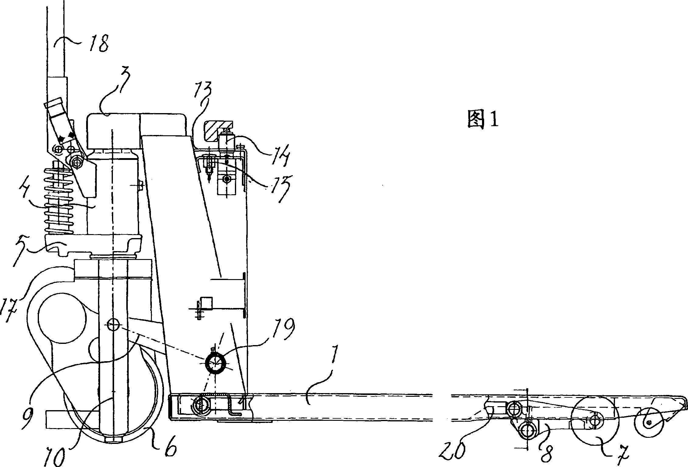
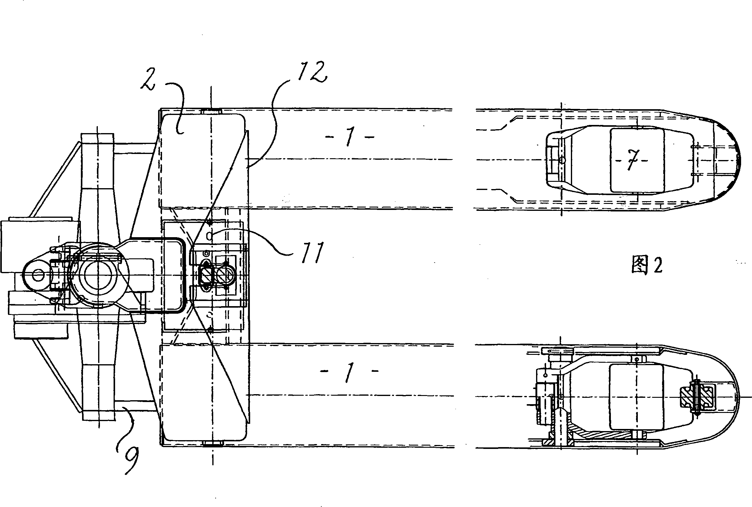
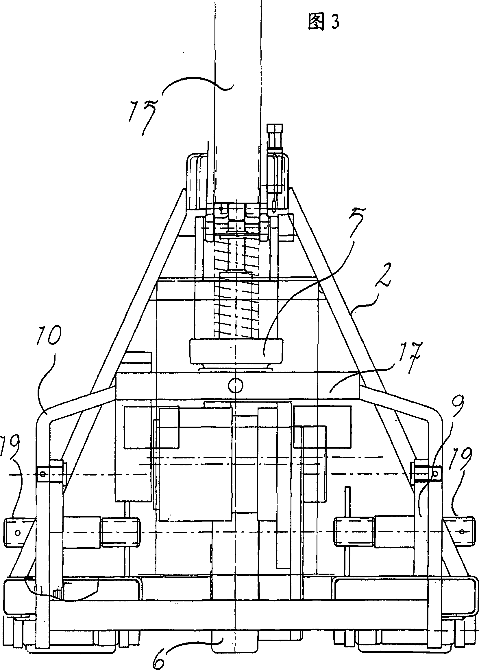
[0011] The cart shown in the accompanying drawings comprises two fork frames 1 identical to common manual carts, wherein the rear ends of the fork frames are connected to the beams, and the upper ends of the two beams 2 extending obliquely upwards, backwards and inwards pass through A bell 3 is connected to accommodate the piston rod of a lifting cylinder 4 , while the lower end of the lifting cylinder is fixed to a pressure plate 5 connected to a guide wheel 6 . On this pressure plate is fixed the pump cylinder of the hydraulic system which can be pivoted up and down by the rudder stock which is pivotally connected to the lift cylinder by the cart.
[0012] At the front end of the lifting fork, support rollers 7 are arranged on arms 8 which are movable between a lowered load lifting position and a raised load free position. Said movement is achieved by means of rods 20 connected in turn to arms 9 connected to two axes 19 of said frame at the rear end of the cart, one on each ...
PUM
 Abstract
Description
Claims
Application Information