
Electronic device energy supply control module and energy supply control method

An electronic device and power control technology, applied in the direction of measurement device, data processing power supply, measurement flow/mass flow, etc., can solve problems such as crash and unstable system power supply.

Inactive Publication Date: 2008-09-10
WISTRON CORP
View PDF0 Cites 13 Cited by
  • Summary
  • Abstract
  • Description
  • Claims
  • Application Information

AI Technical Summary

Problems solved by technology

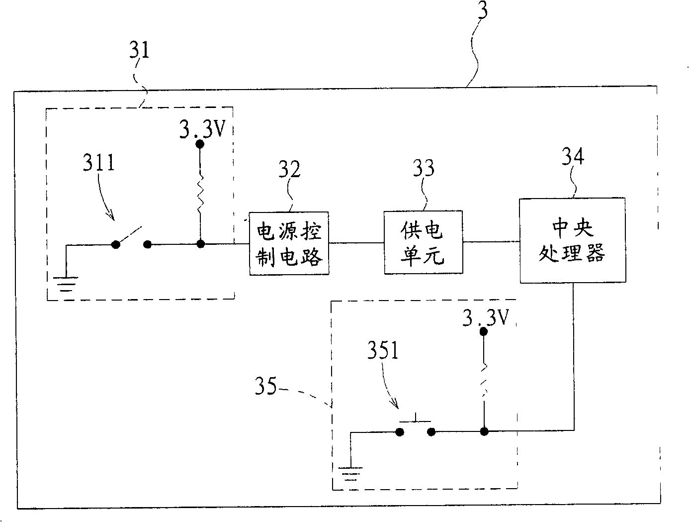
Although this type of electronic device 3 can control the power supply unit 33 to stop supplying power to the central processing unit 34 through the switch 311 to avoid power consumption, but because the switch 311 is a mechanical switch, it is easy to bounce at the moment the switch is toggled, resulting in system power failure. Crash due to unstable supply

Method used


Image

  • Electronic device energy supply control module and energy supply control method
  • Electronic device energy supply control module and energy supply control method
  • Electronic device energy supply control module and energy supply control method

Examples


Embodiment Construction

[0046] The aforementioned and other technical content, features and effects of the present invention will be clearly presented in the following detailed description of a preferred embodiment in conjunction with the accompanying drawings.

[0047] refer to Figure 4 , Figure 4 It is a preferred embodiment of the power control module 41 of the electronic device 4 of the present invention, which is used to realize the power control method of the electronic device of the present invention. The electronic device 4 of this embodiment has a plurality of hardware units 42, and an electrical connection The power supply unit 43 of the hardware unit 42 described above.

[0048] The power control module 41 includes a switch unit 411 , a logic unit 412 , and a CPU 413 electrically connected to the power supply unit 43 . The logic unit 412 is an "OR" logic gate (OR Gate) with two input terminals 414, 415 and an output terminal 416, and its input terminals 414, 415 are electrically connec...


PUM


Abstract

A power supply control module of an electronic device comprises a central processing unit, a switch unit which is electrically connected with the central processing unit and a logical unit. An input end of the logical unit is electrically connected with the switch unit and the central processing unit, and an output end thereof is electrically connected with a power supply unit of the electronic device. A switch signal is output to the central processing unit and the logical unit by pressing the switch unit, thus the logical unit controls the power supply unit to supply power to the central processing unit, at the same time, when the central processing unit judges that the switch signal is a starting signal, a power supply signal is output to the logical unit to control the power supply unit for sustained power supply, when the central processing unit judges that the switch signal is a closing signal, a power-off signal is output to the logical unit to control the power supply unit to stop the power supply.

Description

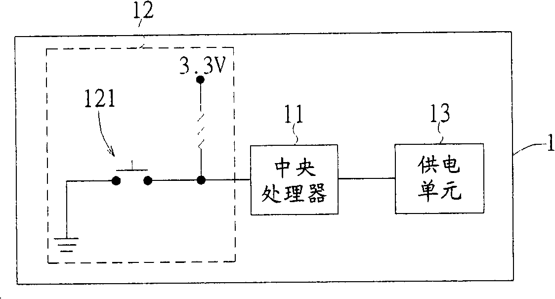
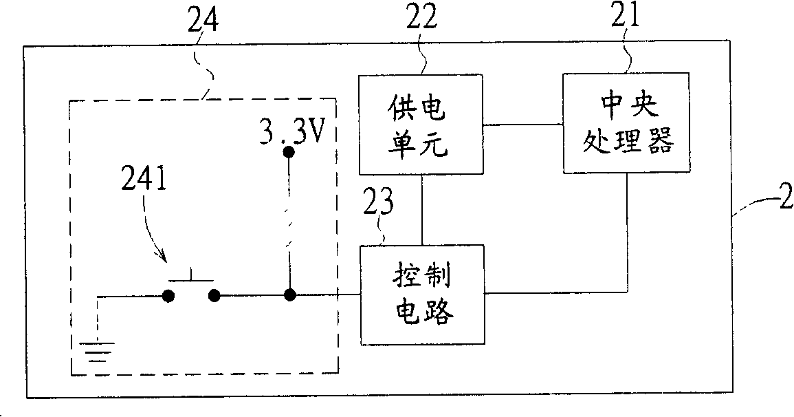
technical field [0001] The invention relates to a control module, in particular to a power control module of an electronic device and a power control method thereof. Background technique [0002] refer to figure 1 , an existing electronic device 1 has a central processing unit 11, a system switch module 12, and a power supply unit 13 for supplying electric power required by the electronic device 1, the power supply unit 13 is electrically connected to the central processing unit 11, and can be An energy storage device detached from the electronic device 1, such as various batteries such as dry batteries and lithium batteries. The system switch module 12 is electrically connected to the central processing unit 11 and has a system switch 121 which can be pressed to control the central processing unit 11 to execute a boot process, so that the electronic device 1 enters a boot mode for user operation. When the electronic device 1 is in the power-on mode, when the system switch...

Claims


Application Information

Patent Timeline
IPC IPC(8): G06F1/26
Inventor 马钦祥
Owner WISTRON CORP
Features
  • Generate Ideas
  • Intellectual Property
  • Life Sciences
  • Materials
  • Tech Scout
  • Unparalleled Data Quality
  • Higher Quality Content
  • 60% Fewer Hallucinations
Learn More