Bandwidth control method and system
A bandwidth control and bandwidth technology, applied in the field of network communication, which can solve the problems of data frame loss, VOQ congestion, and inability to guarantee the QoS of data exchange services, and achieve the effect of avoiding data frame loss and ensuring QoS.
- Summary
- Abstract
- Description
- Claims
- Application Information
AI Technical Summary
Problems solved by technology
Method used
Image

Examples
Embodiment Construction
[0027] In order to make the object, technical solution and advantages of the present invention clearer, the present invention will be described in detail below in conjunction with the accompanying drawings and specific embodiments.
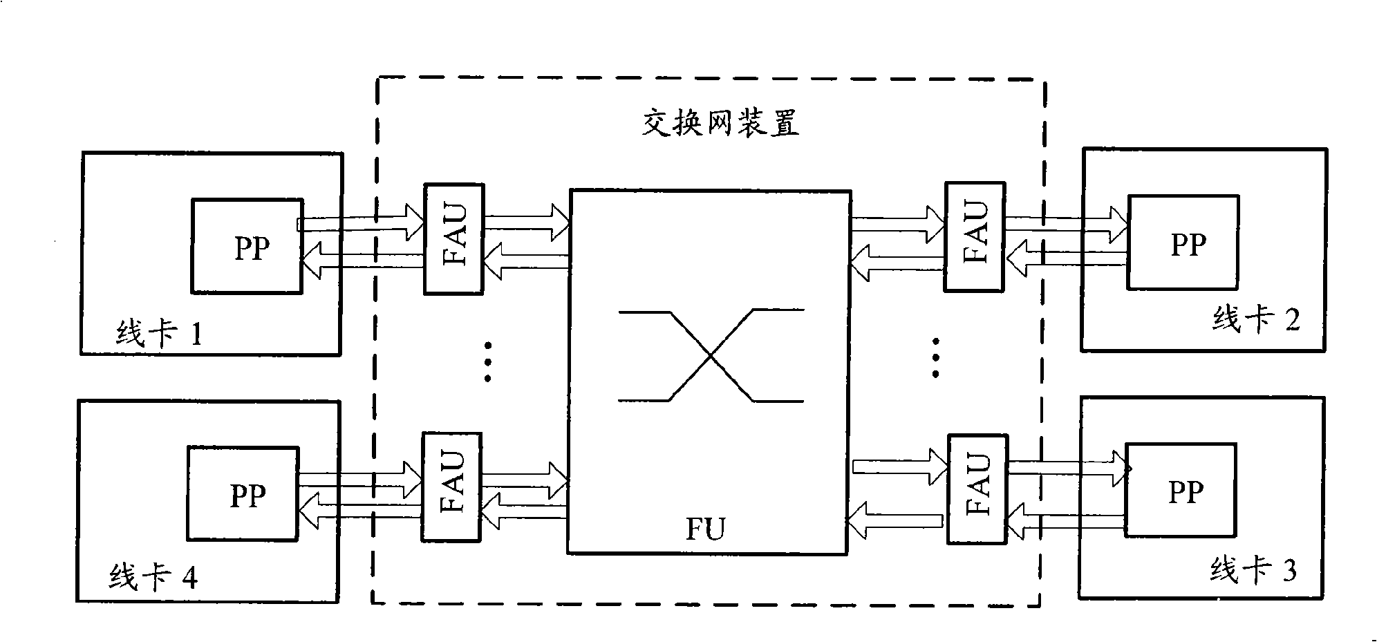
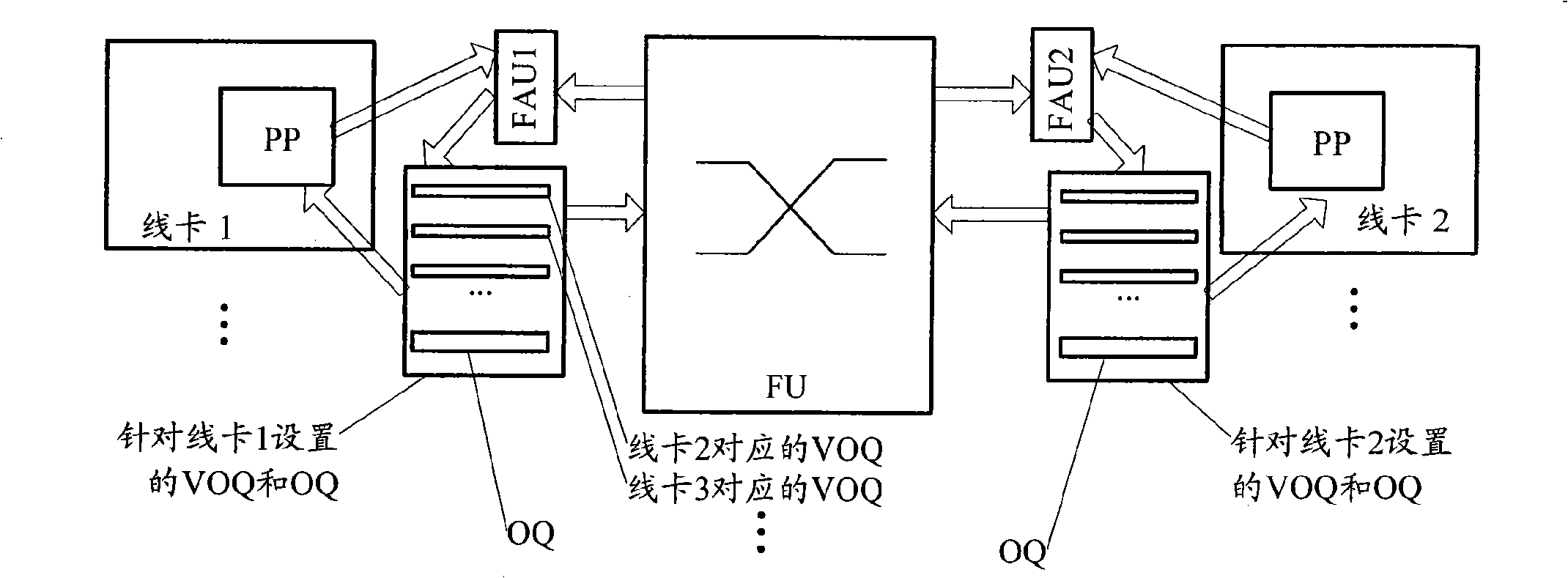
[0028] The method provided by the present invention mainly includes: acquiring the cache state information of the switching network device; when it is determined according to the cache state information that data frame congestion or overflow occurs in the cache of the switching network device, adjusting The data frame sending bandwidth used.
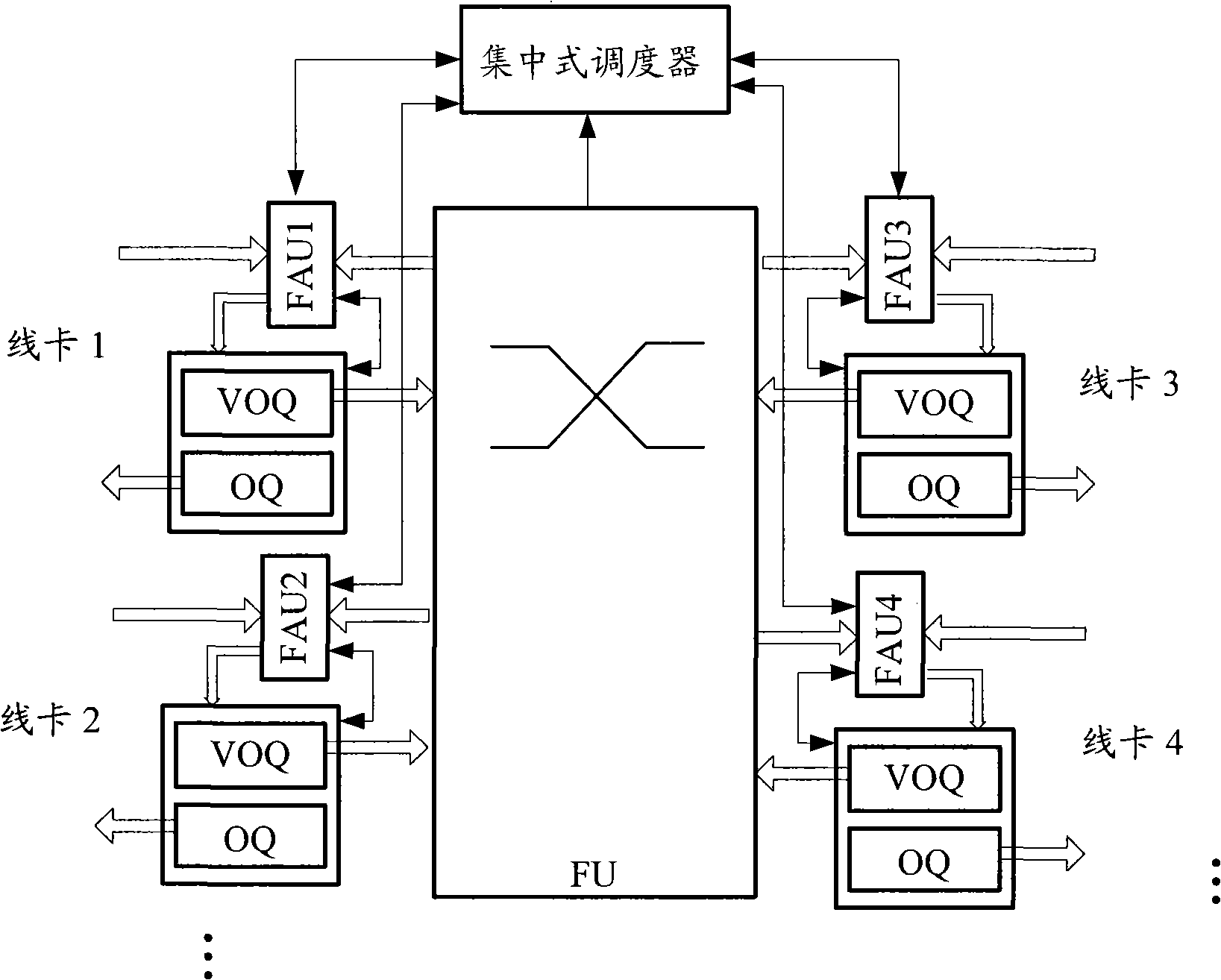
[0029] Wherein, the method may acquire one or more of the following cache status information: VOQ status information, FU cache status information and OQ status information. That is, one or more of these state information are monitored.
[0030] According to the different execution subjects of this method, it can be divided into two types: centralized and distributed. First, the centralized bandwidth control...
PUM
 Abstract
Description
Claims
Application Information