

Hinge and method for manufacturing a hinge
A technology of hinges and pivots, applied in the field of manufacturing hinges, can solve problems such as disadvantages and increased costs
- Summary
- Abstract
- Description
- Claims
- Application Information
AI Technical Summary
Problems solved by technology
Method used
Image

Examples
Embodiment Construction
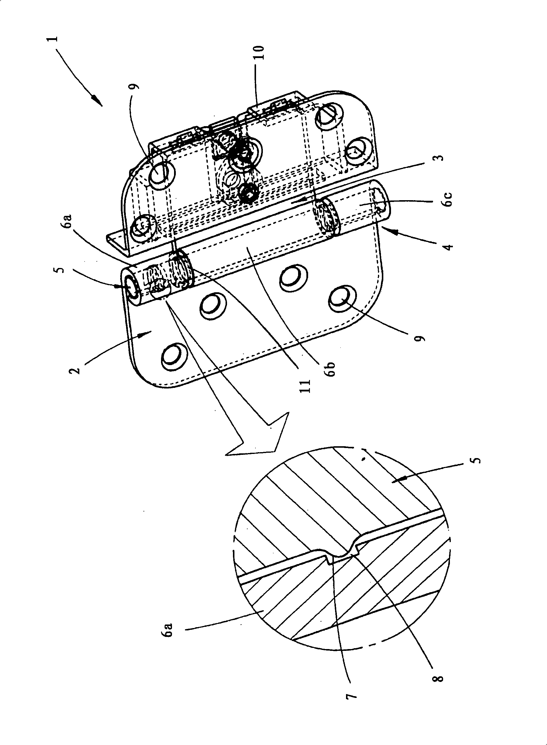
[0010] The hinge 1 shown in the figure comprises a first hinge 2 and a second hinge 3 , both of which are made of sheet metal and connected at a pivot 4 by a pivot pin 5 . An inner pivot eyelet 6b of the second hinge 3 fits between two outer pivot eyelets 6a and 6c of the first hinge. Said pivot eyelets 6a, 6b and 6c are formed by bending those pieces of sheet metal from the first hinge 2 and the second hinge 3, while the pivot eyelets 6a, 6b, 6c are not fully closed. The pivot pin 5 has a radially outwardly protruding thickened region 7 produced by longitudinal compression of the pivot pin 5, thereby forming a circumferential flange as the radially outwardly projected thickened region 7. This radially outwardly protruding thickened region 7 engages in a corresponding inwardly opening groove 8 of a corresponding pivot eye 6a of the first hinge 2 in such a manner that it cannot become loose. The first hinge 2 comprises a second outer pivot eyelet 6c in addition to the first o...
PUM
 Abstract
Description
Claims
Application Information