Apparatus of compact disc

An optical disc device and optical disc technology, applied in the configuration/installation of the head, can solve the problem of slowing down the speed of the seek action

Inactive Publication Date: 2012-09-19
PIONEER TECH (SHANGHAI) CO LTD
View PDF0 Cites 0 Cited by
  • Summary
  • Abstract
  • Description
  • Claims
  • Application Information

AI Technical Summary

Problems solved by technology

As a result, the path-seeking failed, and the above-mentioned path-seeking operation had to be performed again from the focus close action, which greatly reduced the speed of the path-seeking action.

Method used


Image

  • Apparatus of compact disc
  • Apparatus of compact disc
  • Apparatus of compact disc

Examples


Embodiment Construction

[0019] Hereinafter, specific implementation manners of the present invention will be described in detail in conjunction with the accompanying drawings.

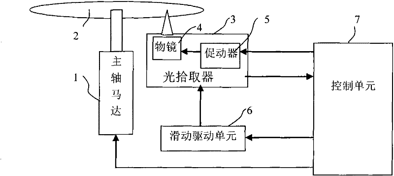
[0020] The optical disc device of the present invention comprises: a spindle motor 1, which carries the optical disc 2, and drives the optical disc 2 to rotate in the plane of the optical disc; and the optical pickup 3 is equipped with an objective lens 4 movable in a direction perpendicular to the surface of the optical disc 2 and a radial direction of the optical disc 2, and drives the objective lens 4 in a direction perpendicular to the surface of the optical disc 2 and An actuator 5 that moves in the radial direction of the optical disc 2; a sliding drive unit 6 that drives the optical pickup 3 to move in the radial direction of the optical disc 2; and a control unit 7 that receives a read signal generated by the optical pickup 3 to generate a tracking The error signal is to divide the optical disc 2 into a plurality of d...


PUM


Abstract

The invention relates to a disc device, which is provided with a main shaft motor, a light collector, a sliding drive unit and a control unit. During tracking to the disc, the control unit carries out the following control: the sliding drive unit is controlled to drive the light collector to lead the light spot to radiate the neighboring of a target track of the disc; a motivating device of the light collector is controlled in virtue of an error tracking signal to lead the light spot radiated by an object lens to do tracking jump to the target track; beside, if the error tracking signal deviates a standard value, the tracking jump is not carried out in a divided zone corresponding to the position where the error tracking signal deviates the standard value. With the invention, quick tracking can also be realized even though the disc protection layer is thin and the face run-out is big.

Description

technical field [0001] The present invention relates to an optical disc device, in particular to an optical disc device capable of fast seeking. Background technique [0002] In conventional optical disc devices, such as figure 1 As shown, it usually includes: a spindle motor 1, the device motor 1 carries the optical disc 2, and drives the optical disc 2 to rotate in the plane of the optical disc; an optical pick-up 3, irradiates the light spot of the laser to the optical disc through the objective lens 4 described later, and receives the optical disc generated by the optical disc. 2 reflected laser light to generate a read signal; direction and the actuator 5 that moves in the radial direction of the optical disc 2; the sliding drive unit 6 drives the optical pick-up 3 to move in the radial direction of the optical disc; and the control unit 7 receives the read signal generated by the optical pick-up 3 The tracking error signal controls the actions of the slide drive unit...

Claims


Application Information

Patent Timeline
Patent Type & Authority Patents(China)
IPC IPC(8): G11B7/09
Inventor 西尾善道
Owner PIONEER TECH (SHANGHAI) CO LTD
Why Eureka
Try Eureka