Supercharge Your Innovation With Domain-Expert AI Agents!

Light-emitting diode unit

A technology of light-emitting diodes and light-emitting diodes, which is used in electrical components, instruments, display devices, etc., can solve the problems of LED units and data sheets that do not correspond, the color of LED units changes, and the brightness and color of light cannot be obtained.

Inactive Publication Date: 2008-11-26
CITIZEN ELECTRONICS CO LTD
View PDF2 Cites 2 Cited by
  • Summary
  • Abstract
  • Description
  • Claims
  • Application Information

AI Technical Summary

Problems solved by technology

[0010] However, in the prior art described above, since the LED unit and the data table are separated, when a single LED element is controlled based on the data table, a selection error of the data table may occur, and thus the LED unit and the data table may be incorrectly selected. Table does not correspond to the situation
Therefore, there is a problem that the luminous color changes in the produced LED unit and predetermined luminance and luminous color cannot be obtained

Method used


Image

  • Light-emitting diode unit
  • Light-emitting diode unit
  • Light-emitting diode unit

Examples


Embodiment Construction

[0025] Next, a detailed description of preferred embodiments of the present invention will be made with reference to the accompanying drawings.

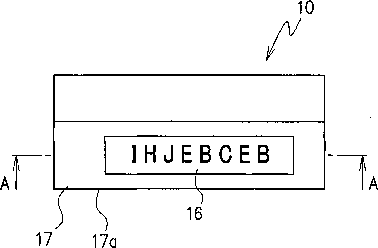
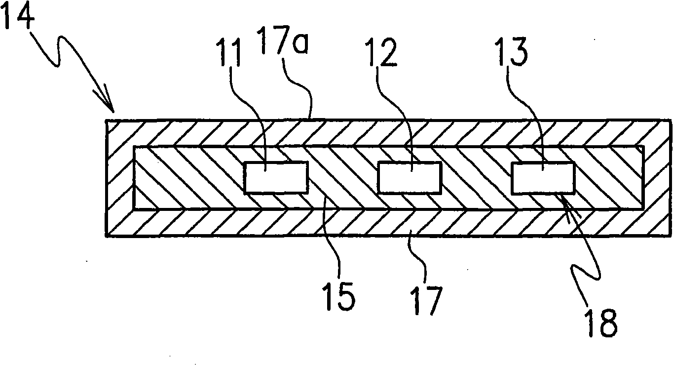
[0026] Figure 1A A light emitting diode (LED) unit 10 according to one embodiment of the invention is shown. The LED unit 10 in this embodiment includes a package 14 and a plurality of LED elements 18 disposed in the package 14 (see Figure 1B ). The package 14 includes an outer frame 17 made of, for example, a white resin material, and, for example, a thermosetting resin 15 disposed inside the outer frame 17 and configured to seal a plurality of LED elements 18 (see Figure 1B ). The resin 15 used to seal the LED elements mounted on the substrate is a translucent resin.

[0027] The LED elements 18 include, for example, a red (R) LED element 11 , a green (G) LED element 12 and a blue (B) LED element 13 , which emit light of three primary colors. By mixing the lights of the three primary colors emitted from the RGB LED elements ...


PUM


Abstract

An LED unit including a frame ( 17 ) and a plurality of LED elements ( 11, 12, 13 ) which emit three primary colors of light and are sealed in the frame ( 17 ), readable characteristic data such as drive conditions, characteristics of each of the plurality of LED elements ( 11, 12, 13 ) being displayed on a surface of the frame.

Description

[0001] Cross References to Related Applications [0002] This application is based on and claims the benefit of priority from Japanese Patent Application No. 2007-066091 filed on March 15, 2007, the entire disclosure of which is hereby incorporated by reference. technical field [0003] The present invention relates to a light emitting diode (LED) unit, in particular an LED unit in which characteristic data of each LED element is displayed on the surface of a package for containing the LED. Background technique [0004] The practice of displaying a lot number or the like on each electronic component is well known. When many details of commonly used small electronic components are required, there is a problem that individual lot numbers of electronic components cannot be distinguished due to insufficient information displayed. Therefore, a technique has been proposed in which lot numbers including production dates and serial numbers of small electronic parts are displayed on...

Claims


Application Information

Patent Timeline
Patent Type & Authority Applications(China)
IPC IPC(8): G09F3/00G09F7/00H01L33/56
CPCH01L2223/54406H01L2223/54433H01L23/544H01L2924/0002H01L2924/00
Inventor 深泽孝一石坂光识
Owner CITIZEN ELECTRONICS CO LTD
Features
  • R&D
  • Intellectual Property
  • Life Sciences
  • Materials
  • Tech Scout
  • Unparalleled Data Quality
  • Higher Quality Content
  • 60% Fewer Hallucinations
Learn More