
Pattern noise removal method and device based on median filter

An image noise and filter technology, applied in the field of image denoising in RGB image space, can solve the problems of poor denoising effect and unsatisfactory denoising effect, and achieve the effect of preventing excessive denoising

Active Publication Date: 2010-04-07
SPREADTRUM COMM (SHANGHAI) CO LTD
View PDF6 Cites 0 Cited by
  • Summary
  • Abstract
  • Description
  • Claims
  • Application Information

AI Technical Summary

Problems solved by technology

[0003] Using the above traditional method for denoising, the denoising effect is not very good, and sometimes new noise is introduced, especially when there are bad pixels in the image, the denoising effect is even more unsatisfactory

Method used


Image

  • Pattern noise removal method and device based on median filter
  • Pattern noise removal method and device based on median filter
  • Pattern noise removal method and device based on median filter

Examples


Embodiment Construction

[0032] The present invention will be further described below in conjunction with the accompanying drawings and embodiments.

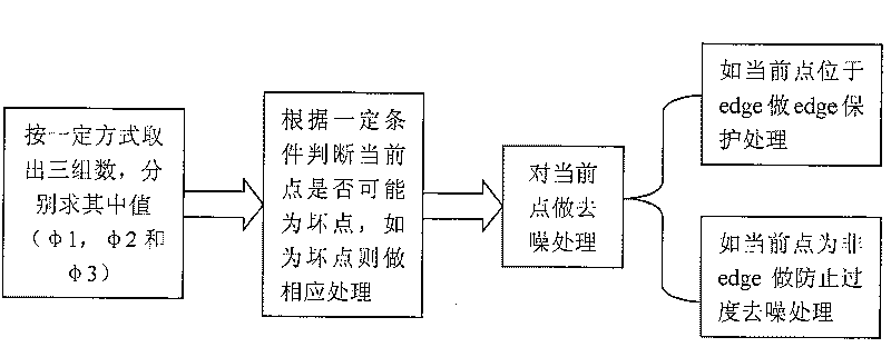
[0033] figure 2 A rough flow of the image noise removal method of the present invention is shown. See figure 2 , first, three groups are taken out from several pixels around the current point according to a certain method, and the respective median values ​​φ1, φ2 and φ3 of the three groups of pixels are calculated through the median filter. Then, according to certain conditions, it is judged whether the current point is a bad point, and if it is a bad point, the bad point is dealt with accordingly. Finally, perform denoising processing on the current point. If the current point is at the edge, perform edge protection processing; otherwise, perform excessive denoising processing on the current point.

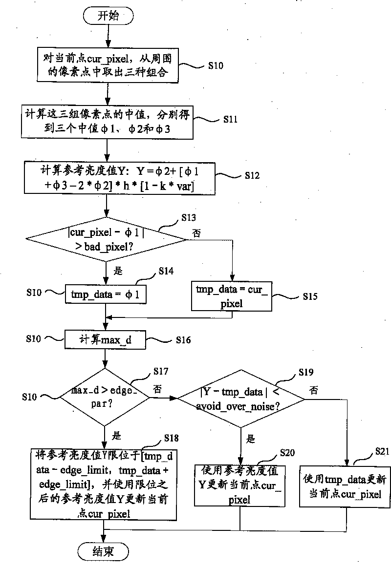
[0034] image 3 right figure 2 Examples are refined, see figure 2 , the following is a detailed description of each step in the image noise rem...


PUM


Abstract

The invention discloses an image noise removing method that is based on a median filter and a device thereof, which is capable of removing linear noise and random noise of a sensor and defect dots ofasensor image and preventing excessive noise removal. The technical scheme of the invention is that: the method comprises the steps that: for the present dot: cur_pixel, three combinations are takenfr om surrounding pixels; medians of each group of pixels: Phi1, Phi2 and Phi3 are calculated; a reference value Y of brightness is calculated: Y is equal to Phi2 plus (Phi1 plus Phi3 minus 2*Phi2)*h*(1 minus k* var), wherein, var is equal to Phi3 minus Phi1; whether the cur_pixel is a defect dot or not is judged, and if the cur_pixel is a defect dot, the tmp_data is caused to be equal to Phi1; ifthecur_pixel is not a defect dot, the tmp_data is caused to be equal to cur_pixel; whether the present dot is located at the edge is judged; if the present dot is at the edge, the Y is located at (tmp_d ata minus edge_limit, tmp_data plus edge_limit), and the cur_pixel is updated; the denoising process is finished. If the present dot is not at the edge, the sizes of (Y-tmp_data) and (avoid_over_noise) are estimated; if (Y-tmp_data) is less than (avoid_over_noise), the Y is used for updating the present dot, or the tmp_data is used for updating the present dot; each dot of the image repeats thesteps. The invention is applied to the field of image denoising.

Description

technical field [0001] The invention relates to image denoising, in particular to an image denoising method and device for Bayer image space or interpolated RGB image space. Background technique [0002] Image denoising is an important unit in the ISP process. There are many methods for image denoising. At present, most image denoising methods based on median filters are very simple. For general traditional image denoising methods, see figure 1 , for the current point, first take three groups from the surrounding pixels in a certain way, and calculate the median values ​​φ1, φ2 and φ3 of these three groups respectively. Then perform denoising processing on the current point, and perform edge protection processing if the current point is on the edge. [0003] Using the above traditional method for denoising, the denoising effect is not very good, and sometimes new noise is introduced, especially when there are bad pixels in the image, the denoising effect is even more unsat...

Claims


Application Information

Patent Timeline
Patent Type & Authority Patents(China)
IPC IPC(8): H04N5/21H04N5/217H04N5/14
CPCG06T5/20H04N5/21G06T5/002G06T2207/20192G06T2207/20032G06T2207/10024
Inventor 张本好冯晓光胡静林福辉
Owner SPREADTRUM COMM (SHANGHAI) CO LTD
Learn More