Fuel supply device

A fuel supply device and fuel supply technology, applied to liquid fuel feeders, charging systems, filtration and separation, etc., can solve the problems of increased cost of fuel supply devices, increased man-hours for assembling fuel supply devices, etc.

Inactive Publication Date: 2009-01-28
DENSO CORP
View PDF1 Cites 10 Cited by
  • Summary
  • Abstract
  • Description
  • Claims
  • Application Information

AI Technical Summary

Problems solved by technology

[0005] In this configuration, the two filter parts are required to manufacture a single fuel supply device, and the use of the two filter parts increases man-hours for assembling the fuel supply device, resulting in an increase in the cost of the fuel supply device

Method used


Image

  • Fuel supply device
  • Fuel supply device
  • Fuel supply device

Examples


Embodiment Construction

[0059] Various embodiments of the present invention will be described below with reference to the accompanying drawings. It should be understood that the components in the following embodiments that are the same or similar to each other are denoted by the same reference numerals in the drawings.

[0060] (first embodiment)

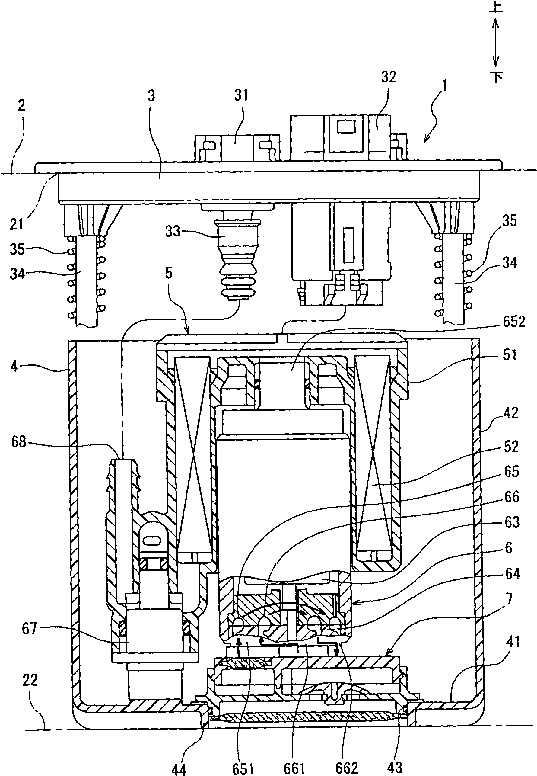
[0061] figure 1 A cross-sectional view is shown in which the fuel supply device 1 is provided in the fuel tank 2 . figure 1 The vertical direction indicated by the arrow in the middle is the direction of gravity, and the fuel tank 2 is installed in the vehicle in this state. The fuel supply device 1 is a device for supplying the fuel in the fuel tank 2 to a fuel consuming device such as an internal combustion engine. like figure 1 As shown, the fuel supply device 1 is inserted into the fuel tank 2 from the opening 21 of the fuel tank 2 so as to be disposed therein and on the bottom surface 22 of the fuel tank 2 . The flange 3 is attached to the openin...


PUM


Abstract

A fuel supply device includes a subtank in a fuel tank, a fuel pump in the subtank having a first pump unit suctioning fuel in the subtank to supply fuel to an external equipment and a second pump unit suctioning fuel outside the subtank to pump fuel into the subtank, and a filter connected to a first suction port of the first unit and a second suction port of the second unit and filtering supply fuel supplied to the equipment and pump fuel pumped into the subtank. The filter includes a case, a first filter, and a second filter. The first filter in a first passage of the case directing fuel in the subtank into the first port filters the supply fuel. The second filter in a second passage of the case directing fuel outside the subtank into the second port filters the pump fuel.

Description

technical field [0001] The present invention relates to a fuel supply device. Background technique [0002] A fuel supply device that can be used to supply fuel stably even when the amount of fuel remaining in the fuel tank decreases is known (for example, refer to US Pat. No. 5,596,970). The fuel supply in US5596970 is housed in a fuel tank. The fuel supply device has a sub-tank for storing part of the fuel in the fuel tank, and a fuel pump accommodated in the sub-tank. The fuel pump includes a first pump unit for pumping fuel in the sub-tank to supply it to the fuel consuming device, and a second pump unit for pumping fuel out of the sub-tank to pump it into the sub-tank. Each suction port of the first and second pump units comprises a filter device equipped with a bag-shaped filter element for separating impurities to be sucked into it. [0003] A pipe for pumping fuel extends from the suction port of the second pump unit through an opening formed in the sub-tank to th...

Claims


Application Information

Patent Timeline
Patent Type & Authority Applications(China)
IPC IPC(8): F02M37/10F02M37/22B01D35/30
Inventor 山田胜久田中正晃河尻千秋
Owner DENSO CORP
Why Eureka
Try Eureka