Wire-tire seat and fishing rob with wire-tire seat

A reel seat and reel technology, applied to fishing rods, fishing, applications, etc., can solve problems such as the impact of fishing operations, and achieve the effect of reducing the sense of gravity

Active Publication Date: 2009-02-04
SHIMANO INC
View PDF1 Cites 1 Cited by
  • Summary
  • Abstract
  • Description
  • Claims
  • Application Information

AI Technical Summary

Problems solved by technology

[0005] Therefore, when holding a fishing rod, the feeling of weight to hold, the weight from the reel to the tip of the slig...

Method used


Image

  • Wire-tire seat and fishing rob with wire-tire seat
  • Wire-tire seat and fishing rob with wire-tire seat
  • Wire-tire seat and fishing rob with wire-tire seat

Examples


Embodiment Construction

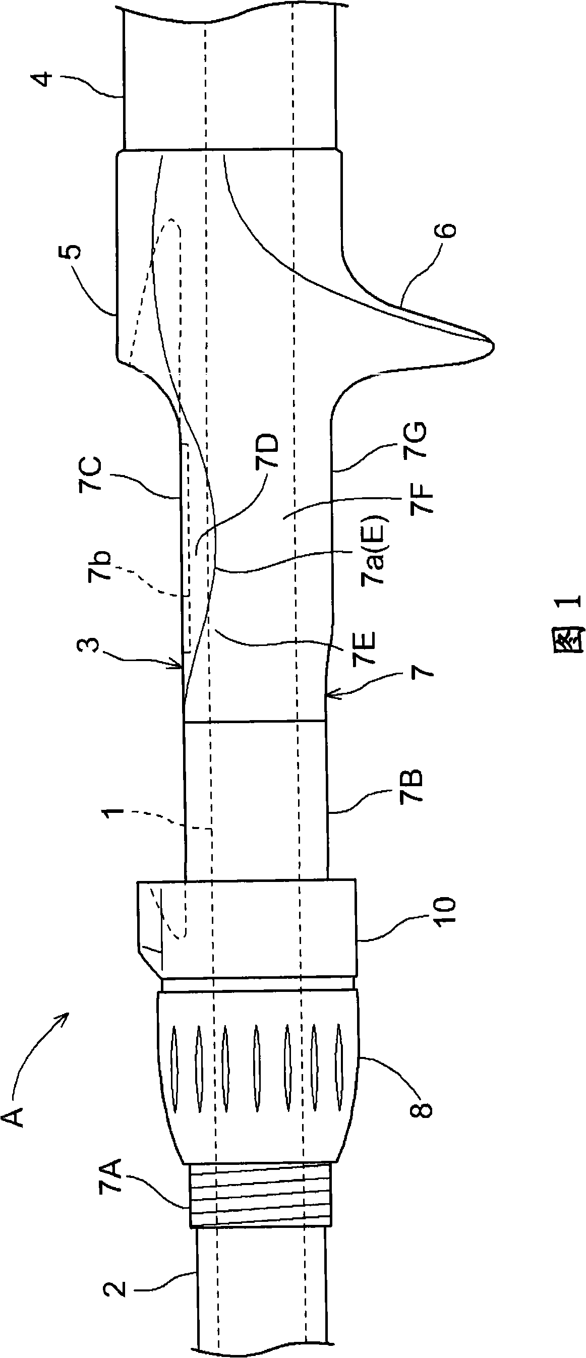
[0035] The fishing rod A used on the fishing boat will be described. As shown in Figures 1 and 6, the structure of the fishing rod A is as follows: a front handle 2 is installed on a cylindrical thin-diameter rod core 1, a reel seat 3 is installed on the rod tail side of the front handle 2, and the rod of the line reel seat 3 The rear handle 4 is installed on the tail side.

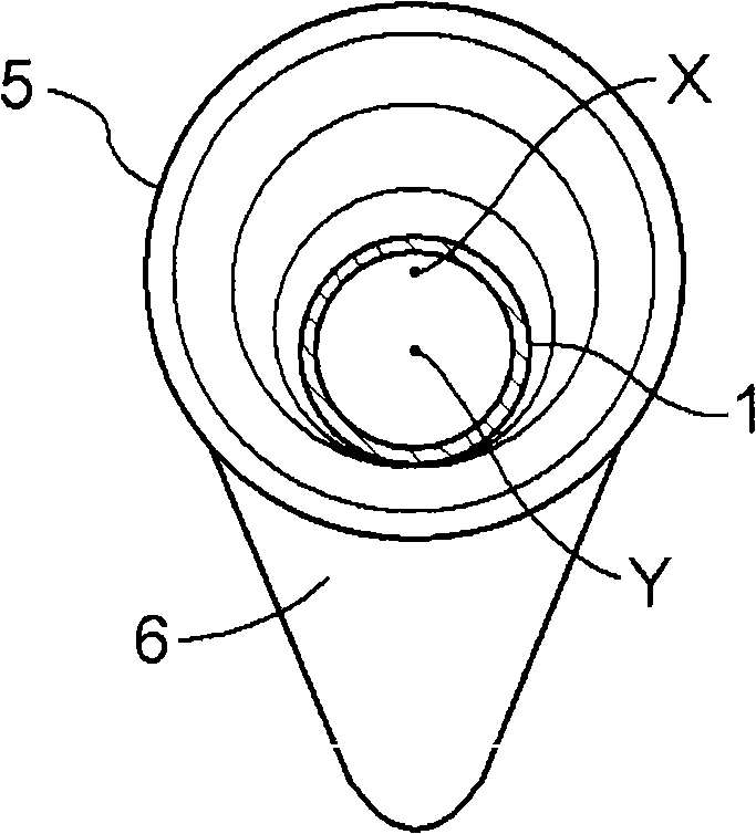
[0036] The structure of the reel base 3 will be described. The structure of the reel seat 3 is as follows, and it is equipped with: a fixed cover 5 arranged on the rod tail side (root side), a seat base 7 integrally formed with the fixed cover 5 and the buckle plate 6, and a rod front end on the base 7. The nut member 8 screwed with the threaded part 7A formed on the upper part (head side), and the movable cover 10 driven and moved by the nut member 8 .

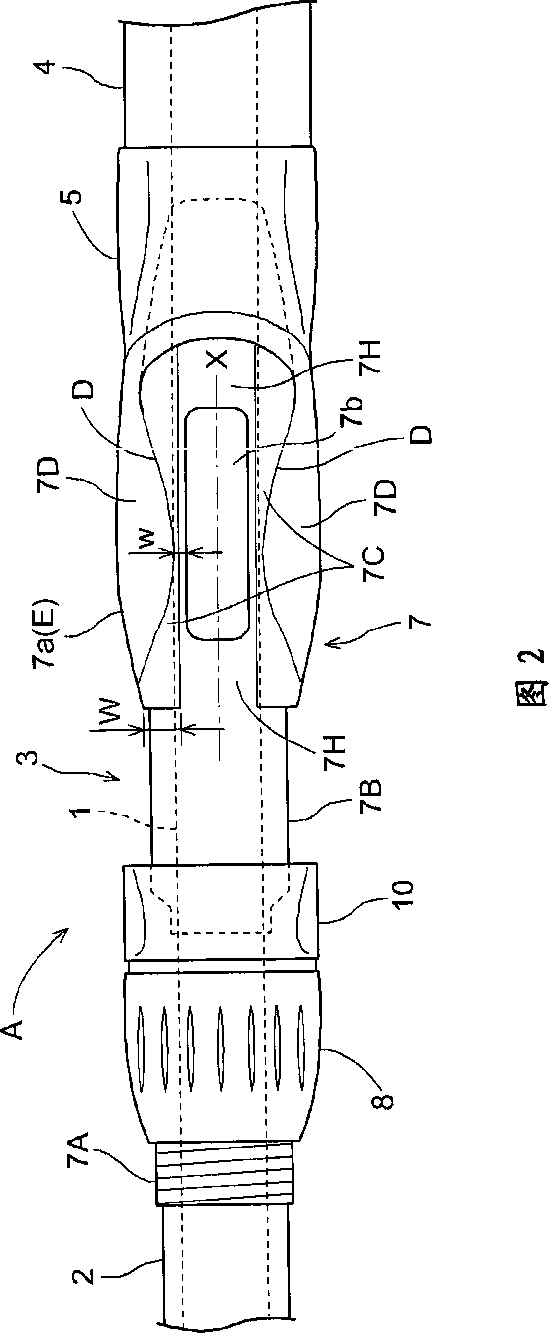
[0037] The base 7 will be described. As shown in Figures 1 and 2, the structure of the seat base 7 is as follows: a cylindrical body is used as the b...


PUM


Abstract

The invention provides a wire wheel seat which is able to reduce weight-bearing sense and lessen situations of losing weight balance by carrying out simple variations to a holding mechanism for holding a wire wheel support of a movable cover. A guide portion (10d) from an inlet side to an inner side is formed at a sidewall surface in an internal space, and an inclination maintaining face portion (10a) is formed at deeper inner side of the guide portion (10d). The spacing between opposite sidewall surfaces are enabled to be smaller as deeper to the inner side, such that the guide portion (10d) and the inclination maintaining face portion (10a) are respectively inclined and inclined angle of the inclination maintaining face portion (10a) is larger than that of the guide portion (10d).

Description

technical field [0001] The present invention relates to a reel holder and a fishing rod having the reel holder, the reel holder has a movable cover having a holding mechanism for holding the reel foot formed in the inner space of the reel foot holding portion . Background technique [0002] To form the above-mentioned holding mechanism, a tapered cylindrical surface whose diameter gradually decreases from the edge of the opening to the inner side is formed in the inner space of the spool leg holding portion. (Patent Document 1) [0003] Patent Document 1: Japanese Patent Application Laid-Open No. 2006-6280 (paragraph 0017, FIG. 2 ) [0004] As described in the above-mentioned documents, in the case where the holding mechanism provided on the reel leg holding portion of the movable cover is constituted by a tapered cylindrical surface, as Figure 7B As shown, since the tapered cylindrical surface is formed at a certain inclination angle, the inclination angle is relatively ...

Claims


Application Information

Patent Timeline
IPC IPC(8): A01K87/06
Inventor 川岛公一桥本浩志远藤周一
Owner SHIMANO INC
Why Eureka
Try Eureka