Method, system and node equipment for implementing district switch by mobile terminal

A mobile terminal and cell handover technology, applied in the direction of radio/inductive link selection arrangement, selection device, etc., can solve the problems of mobile terminal and network short-term disconnection, service performance impact, call drop during handover preparation stage, etc., to improve the overall Service transmission quality, improve downlink transmission quality, and facilitate the effect of smooth transition

Active Publication Date: 2009-02-25
DATANG MOBILE COMM EQUIP CO LTD
View PDF0 Cites 32 Cited by
  • Summary
  • Abstract
  • Description
  • Claims
  • Application Information

AI Technical Summary

Benefits of technology

The technology described in this patented describes how an access point (AP) server helps determine best-performing cells from different devices connected through wireless communication networks. It then selects one device amongst these candidates for connection when it needs more bandwidth than others due to its poor signal strength. This ensures stable connections even over longer periods without interruptions. Additionally, the use of multiple antennas allows simultaneous reception/transmission signals across both upstream and downstream directions while maintaining good signal integrity throughout the procedure. Overall, this approach enhances efficient utilization of available spectrum within the limited space around us.

Problems solved by technology

This patented technical solution describes how quickly switching off signals transmitted over different paths may result in wasted radio access bandwidth due to unnecessary signal processing procedures performed beforehand. Additionally, current methods require multiple steps involving both sending an acknowledgement/repair order back along with serving requests from the destination base stations themselves, further slowdown the overall procedure.

Method used


Image

  • Method, system and node equipment for implementing district switch by mobile terminal
  • Method, system and node equipment for implementing district switch by mobile terminal
  • Method, system and node equipment for implementing district switch by mobile terminal

Examples


Embodiment 1

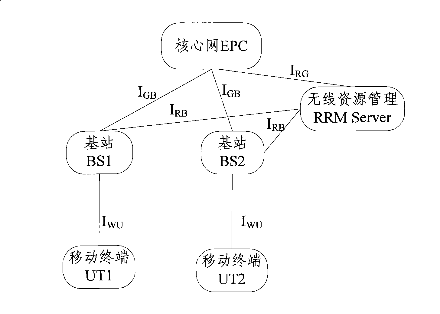
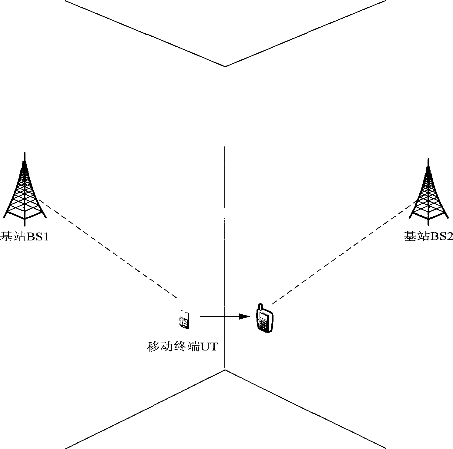
[0068] see image 3 , in this embodiment, there is no subordinate relay of the base station in the network, the base station BS1 is the source node for the initial attachment of the mobile terminal UT, the base station BS2 is the target node of the mobile terminal UT, BS1, BS2, BS3 ( image 3 not shown) form a set of downlink nodes, and in this embodiment both the target node and the downlink node are base stations. When the mobile terminal UT moves from left to right, that is, from the coverage of BS1 to the coverage of BS2, the handover process of UT is as follows: Figure 4 shown, including the following steps:

[0069] Step 401: The mobile terminal initially attaches to BS1. When the terminal moves to the cell boundary and triggers the handover threshold, it will send a measurement report to the RRM Server. The measurement report contains a list of candidate target nodes {BS1, BS2, BS3, BS4... ..}.

[0070] Step 402: The RRM Server selects the optimal node in the candid...

Embodiment 2

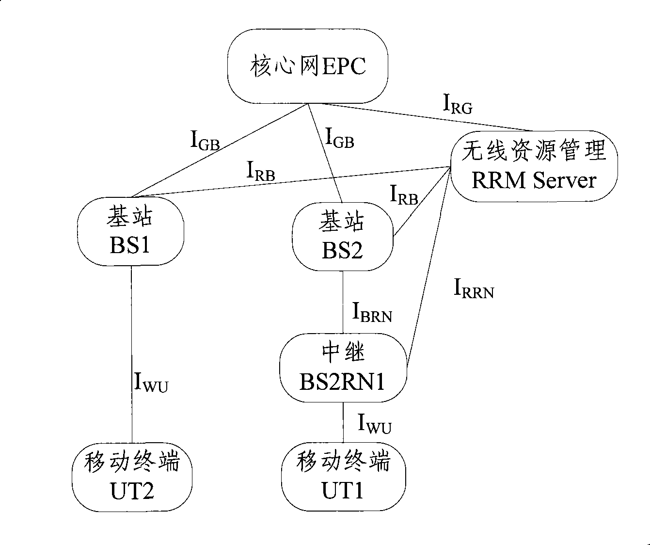
[0097] see Figure 5 , in this embodiment, there is a subordinate relay of the base station in the network, the base station BS1 is the source node for the initial attachment of the mobile terminal UT and has no subordinate relay, BS2RN1 and BS2RN2 are the subordinate relays of the base station BS2, and BS2RN2 is the target node of the mobile terminal UT , BS1, BS2, RN2, BS3 ( Figure 5 not shown in ) to form a downlink node set. When the mobile terminal UT moves from left to right, that is, from the coverage of BS1 to the coverage of BS2, the handover process of UT is as follows: Image 6 shown, including the following steps:

[0098] Step 601: The mobile terminal UT initially attaches to BS1. When the mobile terminal UT moves to the cell boundary, a handover threshold is triggered, and a measurement report will be sent to the RRM Server. The measurement report contains a list of candidate target nodes {BS1, BS2RN1, BS2RN2, BS3...}.

[0099] Step 602: The RRM Server selec...

Embodiment 3

[0127] see Figure 7 , in this embodiment, there are relays subordinate to the base station in the network, BS1RN1 and BS1RN2 are the relays subordinate to the base station BS1, BS1RN2 is the source node for the initial attachment of the mobile terminal UT, and the base station BS2 is the target node of the mobile terminal UT and has no subordinate relays Next, BS1RN1, BS1RN2, BS2, and BS3 form a downlink node set. When the mobile terminal UT moves from left to right, that is, from the coverage of BS1 to the coverage of BS2, the handover process of UT is as follows: Figure 8 shown, including the following steps:

[0128] Step 801: The mobile terminal UT initially attaches to BS1RN2. When the UT moves to the cell boundary, a handover threshold is triggered, and a measurement report will be sent to the RRM Server. The measurement report contains a list of candidate target nodes {BS1RN1, BS1RN2, BS2, BS3...}.

[0129] Step 802: The actions performed are similar to the step 60...


PUM


Abstract

The invention discloses a method for mobile terminal to realize channel switch, which includes the following steps: during the switch preparation stage, RRM Server ensures a target node and a down node-set, and the down node-set begins to provide downstream data for the mobile terminal during the switch preparation stage; during the switch stage, the mobile terminal switches the uplink into the target node assured by RRM Server or mobile terminal, then the downstream data is sent by down node-set; after the switch, the down node focus the node release resources except the target node, and the target node provides up-down service for mobile terminal. The invention also discloses a system and a RRM Server for mobile terminal to realize channel switch, using the method, system and RRM Server can reduce drop-calls and resource occupation of mobile terminal in switch process, and realize continuous receiving of downstream data in the whole switch process by mobile terminal, and improves transmission service quality of mobile terminal.

Description


Claims


Application Information

Patent Timeline
Owner DATANG MOBILE COMM EQUIP CO LTD
Why Eureka
Try Eureka