
Uplink bandwidth allocation method and optical line terminal

A bandwidth allocation method and optical line terminal technology, which is applied in the field of communication, can solve problems such as system resource occupation, and achieve the effect of reducing allocation frequency and interaction

Active Publication Date: 2009-03-11
ZTE CORP
View PDF0 Cites 14 Cited by
  • Summary
  • Abstract
  • Description
  • Claims
  • Application Information

AI Technical Summary

Problems solved by technology

[0006] Considering the problem that the DBA mechanism of the current PON system frequently and repeatedly allocates bandwidth to cause a large amount of system resources to be occupied, the present invention is proposed. Therefore, the main purpose of the present invention is to provide an uplink bandwidth allocation method and an optical line terminal to solve the problems in the related art. The above problems

Method used


Image

  • Uplink bandwidth allocation method and optical line terminal
  • Uplink bandwidth allocation method and optical line terminal
  • Uplink bandwidth allocation method and optical line terminal

Examples


example 1

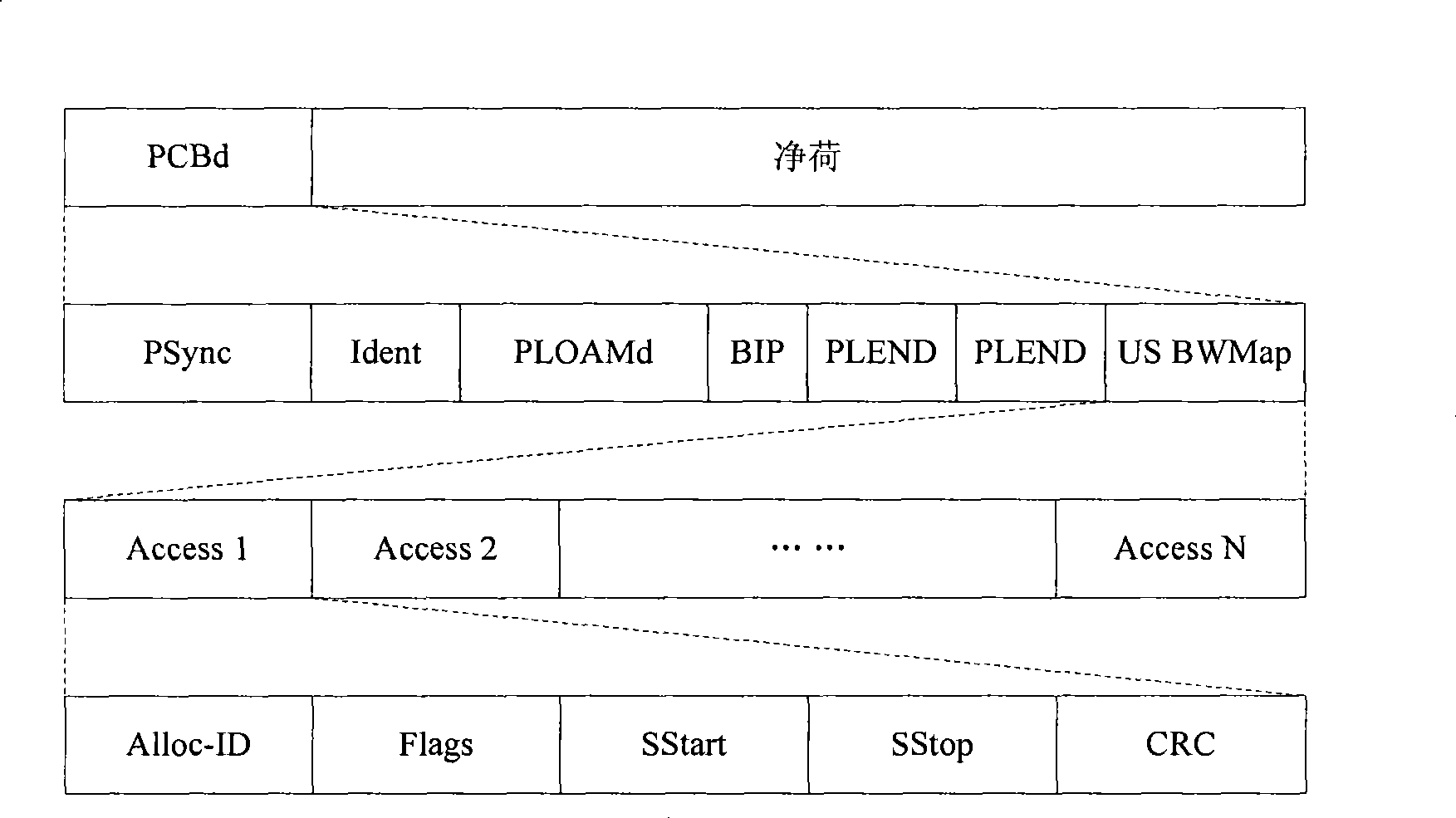
[0045] In this example, the processing procedure of the present invention will be described by taking the GPON system as an example. The uplink bandwidth allocation format of GPON system is as follows: figure 1 As shown, the 6-0 bit of the Flags field is a reserved field, and this embodiment uses the reserved field to increase the corresponding option mark, and the 6-0 bit of the Flags field is designed as follows:

[0046] Bits 6-5: When set to 11, it means permanent use; when set to 01, 10, it means non-permanent use; when set to 00, it means unallocated.

[0047] Bit 4-0: valid cycle number of uplink bandwidth allocation (that is, the length of the above predetermined cycle), this field is only valid when bits 6-5 are set to 01 and 10 values.

[0048] For the upstream bandwidth allocated to the ONU for permanent use, the OLT sets the bits 6-5 of the corresponding Flags domain to 11 (corresponding to the above-mentioned step S302) when allocating, and the ONU obtains the up...

example 2

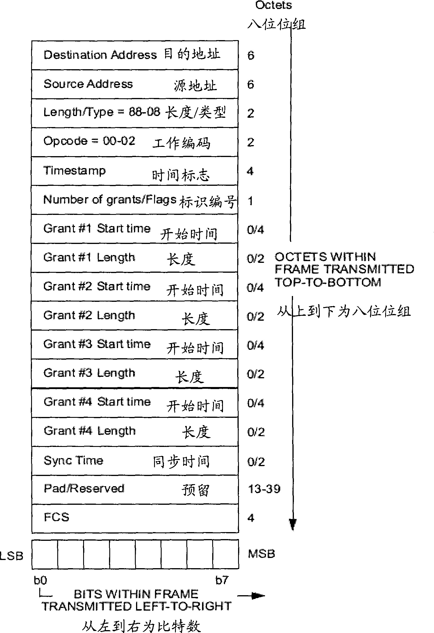
[0052] In this example, the processing procedure of the present invention will be described by taking the EPON system as an example. The upstream bandwidth allocation of the EPON system is realized through the GATE (channel) message, such as figure 2 As shown, wherein at least 13 bytes are reserved domains, and the present embodiment uses the 4 bytes behind the Sync time field to indicate the purposes of 4 Grants in the reserved domains, which are respectively defined as Flags1, Flags2, Flags3, Flags4, Flags1, Flags2, Flags3, Flags4 will be described in detail below.

[0053] Flag1: bit 7-6 (11-permanent use, 01, 10-non-permanent use, 00-deallocation), bit 5-0 (valid period number of uplink bandwidth allocation, this field is only 01 or 01 in bit 7-6 10 value is valid).

[0054] Flag2: bit 7-6 (11-permanent use, 01, 10-non-permanent use, 00-deallocation), bit 5-0 (valid period number of uplink bandwidth allocation, this field is only 01 or 01 in bit 7-6 10 value is valid)....


PUM


Abstract

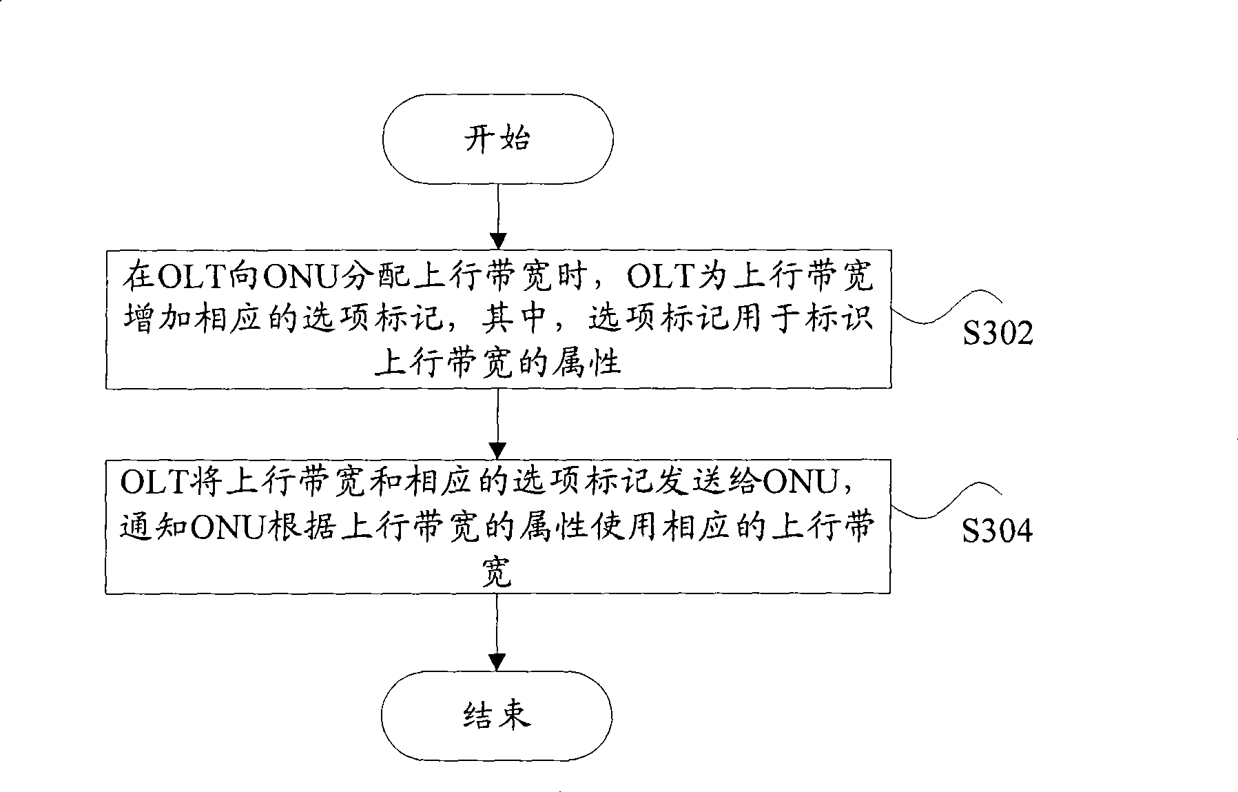
The invention discloses an upstream bandwidth allocation method and an optical-circuit terminal, the method comprises: when the optical-circuit terminal allocates the upstream bandwidth to an optical-fiber network, the optical-circuit terminal adds a corresponding option mark for the upstream bandwidth, wherein the option mark is used for indicating the attribute of the upstream bandwidth; the optical-circuit terminal sends the upstream bandwidth and the corresponding option mark to an optical-fiber network unit, and notifies the optical-fiber network unit to use the corresponding upstream bandwidth according to the attribute of the upstream bandwidth. By the process, the interaction between OLT and ONU can be reduced, the allocation frequency of the upstream bandwidth can be lowered, the occupation of the downstream bandwidth is reduced, and the ONU is facilitated to collectively plan the application of the upstream bandwidth.

Description

technical field [0001] The present invention relates to the communication field, and in particular, relates to an uplink bandwidth allocation method and an optical line terminal. Background technique [0002] Generally, a Passive Optical Network (PON) system consists of an Optical Line Terminal (OLT), an Optical Network Unit (ONU) and an Optical Distribution Network, Abbreviated as ODN) composition. [0003] Wherein, the ODN is generally a point-to-multipoint structure, and an OLT can be connected to multiple ONUs through the ODN, for example, the International Telecommunications Union-Telecommunications Standardization Sector (International Telecommunications Union-Telecommunications standardization sector, referred to as ITU-T) G.984 series Gigabit PON (GPON for short) system, Institute for Electrical and Electronic Engineers (IEEE for short) 802.3 series Ethernet PON (EPON for short) system, etc. . [0004] In a PON system (such as EPON, GPON system) based on Time Divi...

Claims


Application Information

Patent Timeline
Patent Type & Authority Applications(China)
IPC IPC(8): H04L12/56H04Q11/00
CPCH04L41/0896H04Q2213/1301H04Q2011/0064H04Q11/0067H04Q2011/0088
Inventor 张伟良袁立权
Owner ZTE CORP
Learn More