
Twist-beam rear axle for a vehicle

A guide rod, rear axle technology, applied in the direction of vehicle components, cantilevers mounted on pivots, interconnection systems, etc., to achieve the effect of suppressing oversteer movement

Inactive Publication Date: 2009-03-18
GM GLOBAL TECH OPERATIONS LLC
View PDF1 Cites 7 Cited by
  • Summary
  • Abstract
  • Description
  • Claims
  • Application Information

AI Technical Summary

Problems solved by technology

Although the problem can be solved satisfactorily by this measure, it requires the provision of an additional bogie for supporting the composite link rear axle, which is not always desirable depending on the vehicle type

Method used


Image

  • Twist-beam rear axle for a vehicle

Examples


Embodiment Construction

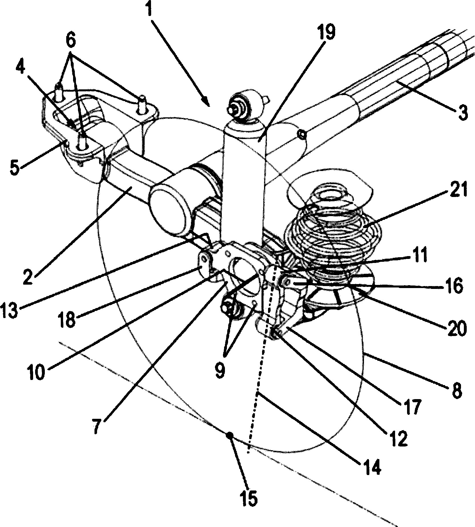
[0024] exist figure 1 An embodiment of a composite control-bar rear axle of a motor vehicle according to the invention is shown schematically with the reference number 1 . For simplicity, in figure 1 Only the shaft section of the composite guide rod rear axle 1 supporting the left rear wheel is shown in the figure. In the same way, the composite link rear axle is equipped with an axle section supporting the right rear wheel, which is designed symmetrically to the axle section supporting the left rear wheel.

[0025] The composite link rear axle 1 thus comprises two rigid longitudinal tie rods 2 extending substantially in the longitudinal direction of the vehicle, which are passed through a bending-resistant, but not torsion-resistant, cross-member extending substantially in the transverse direction of the vehicle 3 interconnected. The crossbar 3 , which is connected to the trailing rod 2 , for example by welding, serves as a stabilizer when the two wheels supported by the c...


PUM


Abstract

A torsion-beam rear axle of a vehicle, more preferably motor vehicle, is provided with two rigid trailing arms, which with their one end are each mounted on a vehicle body in a manner capable of being swiveled and at the other end of which a wheel carrier is each attached for the rotatable mounting of a vehicle wheel about its wheel center axis, as well as with a torsionally soft cross-tie connecting the two trailing arms with each other. Each wheel carrier, by means of at least three elastic wheel carrier bearings is fixed to the trailing arm when viewed in forward driving direction of the vehicle, at least two wheel carrier bearings are arranged behind the wheel center axis, and at least one wheel carrier bearing is arranged in front of the wheel center axis in such a manner that through the two wheel carrier bearings arranged behind the wheel center axis to define a swivel axis for the swiveling of the wheel carrier relative to the trailing arm.

Description

technical field [0001] The invention belongs to the field of chassis technology, and relates to a composite guide rod rear axle of a vehicle, in particular to a composite guide rod rear axle of an automobile. Background technique [0002] Composite link rear axles are known per se to those skilled in the art of chassis technology. For this reason, compound link rear axles are used in large numbers in modern motor vehicles, for example in the models "Opel Corsa" and "Opel Astra" of the applicant. Such a type of compound link rear axle is described in the patent literature, for example in European patent EP0681932B2 and in the applicant's German publication DE 10200403208A1. [0003] Such a composite link rear axle comprises two rigid trailing rods, which are arranged at their front ends on the vehicle body or on the bogie so that they can be swiveled about a swivel axis arranged transversely to the longitudinal direction of the vehicle, and on their rear sides Wheel carrier...

Claims


Application Information

Patent Timeline
Patent Type & Authority Applications(China)
IPC IPC(8): B60G21/055B60G3/14
CPCB60G7/008B60G2200/445B60G3/26B60G2204/148B60G2200/462B60G2200/21B60G21/051
Inventor 格尔德·比茨于尔根·西贝尼克埃克哈特·多赫勒
Owner GM GLOBAL TECH OPERATIONS LLC
Learn More