Supercharge Your Innovation With Domain-Expert AI Agents!

Quantisation indication circuit

An indication circuit and indication technology, which is applied in the layout of electric light circuits, electric light sources, lighting devices, etc., can solve the problems of inability to know the frequency, temperature, and voltage status of the motherboard in real time, affecting performance, and damage.

Active Publication Date: 2009-03-18
ASUSTEK COMPUTER INC
View PDF0 Cites 0 Cited by
  • Summary
  • Abstract
  • Description
  • Claims
  • Application Information

AI Technical Summary

Problems solved by technology

[0004] However, this is only presented on the screen. For computer game players, the main board is often overclocked, but not every player will remember to adjust the operating frequency of the main board to the normal value after the game is over, and not every After the computer is turned on, gamers always remember to check the previous overclocking settings through the BIOS or control software, so that the mainboard is often used for a long time overclocking, so it is prone to overheating and affect performance, or even damage
In addition, using the method of displaying values ​​on the screen requires constant switching of screens to obtain the required data. For those who are using other tasks, they cannot know the frequency, temperature, and voltage status of the motherboard in real time, which is very inconvenient.

Method used


Image

  • Quantisation indication circuit
  • Quantisation indication circuit
  • Quantisation indication circuit

Examples


Embodiment Construction

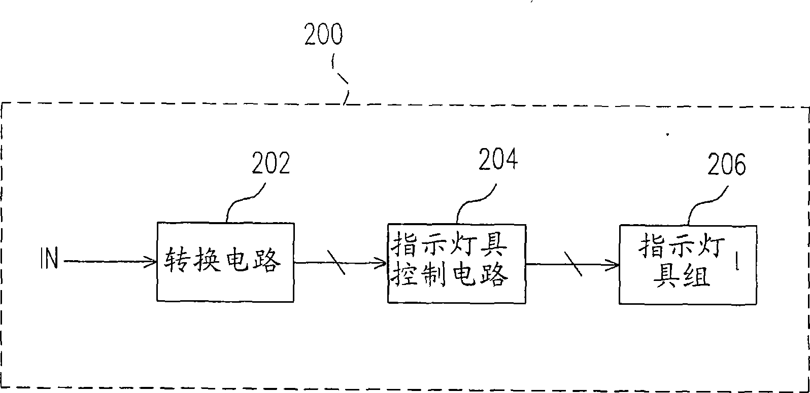
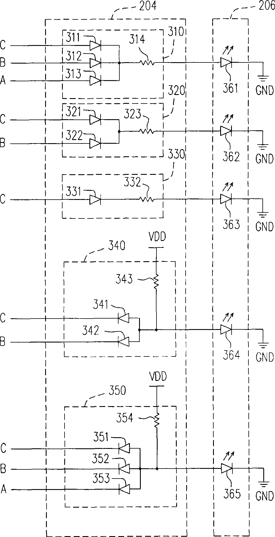
[0015] figure 2 It is a block diagram of a quantization indicator circuit according to an embodiment of the present invention. The quantization indicator circuit is suitable for being disposed on a circuit board, such as a main board or a component carrier board of any electronic product. Please refer to figure 2 , where the mark 200 means the circuit board. The quantitative indication circuit includes a conversion circuit 202, an indicator lamp control circuit 204 and an indicator lamp group 206, and the indicator lamp group 206 has a plurality of indicator lamps (refer to image 3 361~365). The conversion circuit 202 is used for receiving a numerical signal IN from the circuit board 200 , and the numerical signal IN can be a frequency value, a voltage value or a temperature value. For example, the conversion circuit 202 can be designed as a plurality of comparators, and cooperate with multiple critical values ​​inside the conversion circuit 202 to compare or judge wheth...


PUM


Abstract

The invention relates to a quantization indicating circuit, which comprises an indicating lamb set, a switching circuit and an indicating lamb control circuit, wherein the indicating lamb set is provided with a plurality of indicating lambs, a plurality of critical values are preset in the switching circuit for generating a comparison result after comparison with a numerical signal of a circuit board, the comparison result is converted into an output of a plurality of control bits, and the indicating lamb control circuit is coupled between the indicating lamb set and the switching circuit to control the lighted number of the indicating lambs according to the output of the control bits.

Description

technical field [0001] The invention relates to a quantization indicating circuit, in particular to a quantizing indicating circuit on a motherboard. Background technique [0002] For computer users, if they want to adjust the operating frequency and voltage of the motherboard, they must be set through the basic input / output system (BIOS), or through the control software applied in the window interface. to set, and these setting values ​​will be displayed on the screen when setting, so that the user can understand the current setting status of the motherboard. The following will be figure 1 Let me explain a little bit. [0003] figure 1 Shown is a schematic diagram of the coupling of the motherboard monitoring circuit in the known motherboard. Please refer to figure 1 , wherein the mark 100 represents the main board, 102 represents the monitoring circuit of the main board, and 110 represents the screen. Taking frequency adjustment as an example, when the user sets the ...

Claims


Application Information

Patent Timeline
Patent Type & Authority Applications(China)
IPC IPC(8): G06F11/32H05B37/02
Inventor 林秉民吴潮崇何进福
Owner ASUSTEK COMPUTER INC
Features
  • R&D
  • Intellectual Property
  • Life Sciences
  • Materials
  • Tech Scout
  • Unparalleled Data Quality
  • Higher Quality Content
  • 60% Fewer Hallucinations
Learn More