Negative-pressure drainage tube

A technology of negative pressure drainage and drainage section, which is applied in the field of drainage tube and can solve problems such as tissue damage

Inactive Publication Date: 2011-01-19
曲乐丰 +1
View PDF1 Cites 0 Cited by
  • Summary
  • Abstract
  • Description
  • Claims
  • Application Information

AI Technical Summary

Problems solved by technology

These features are not beneficial to clean or slightly infected wounds with little exudate and thin liquid, because none of the above changes can prevent local tissue from being sucked into the drainage hole when the negative pressure in the tube is high, resulting in drainage. Blockage of pores and possible damage to tissue

Method used


Image

  • Negative-pressure drainage tube
  • Negative-pressure drainage tube
  • Negative-pressure drainage tube

Examples


Embodiment 1

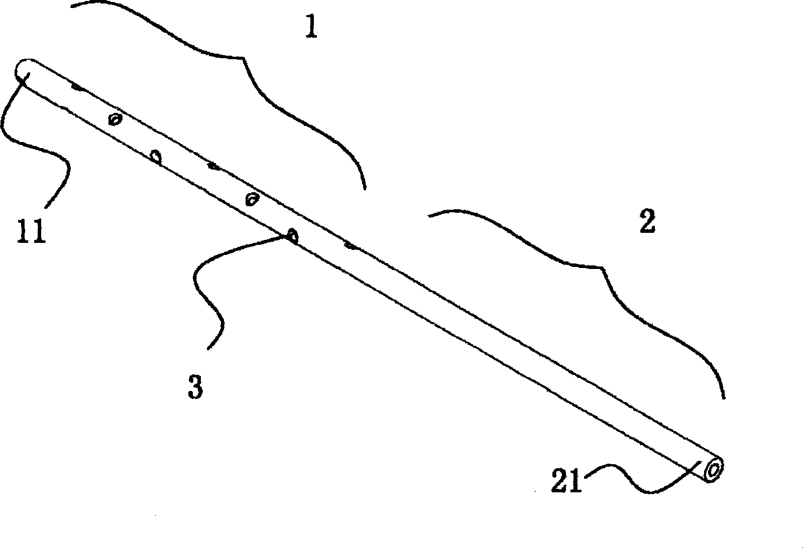
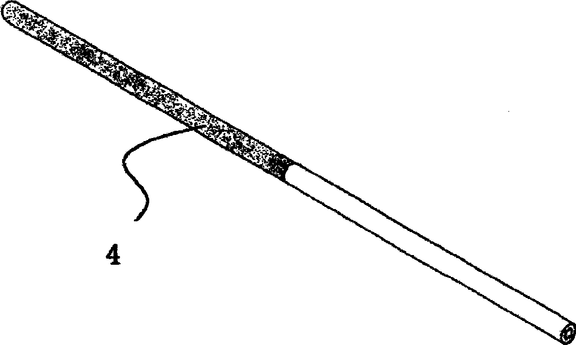
[0017] See attached Figure 2-3 , on the basis of the existing silicone rubber or soft plastic negative pressure drainage tube with multiple drainage holes, the outer diameter of the drainage section is slightly reduced, and the reduction is about 2 times the thickness of the non-woven fabric to be covered times. The non-woven fabric is made into a bag 4 suitable for the thickness of the above-mentioned drainage section, so that it can be tightly covered outside the drainage section, covering all the drainage holes, and the opening of the bag is fixedly combined with the drainage tube, and connected with the drainage tube Smooth transition. In order to make the drainage effect better, the outer surface of the drainage section where the drainage tube is covered in the non-woven bag can be provided with a large number of longitudinal or oblique fine grooves communicating with the drainage holes.

Embodiment 2

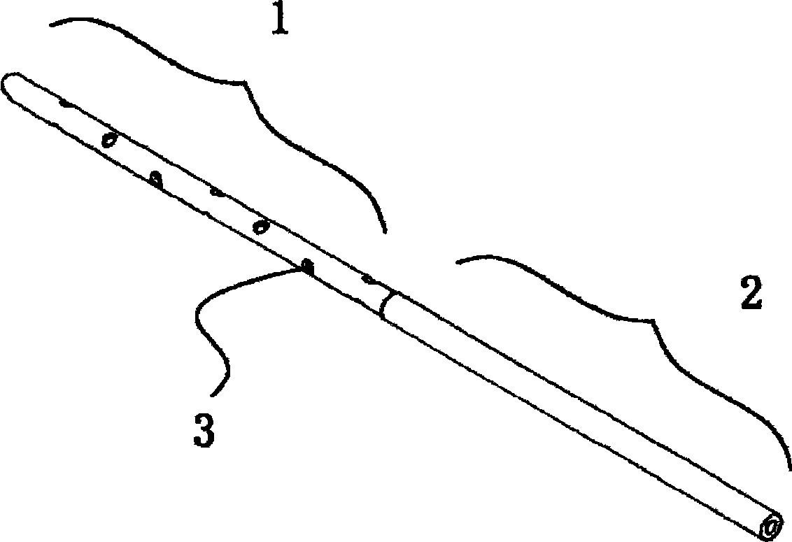
[0019] See Figure 3-4 , on the basis of the existing negative pressure drainage tube with multiple drainage side holes made of silicone rubber or soft plastic, three longitudinal grooves 5 are arranged on the outer surface of the drainage section of the drainage tube, and the drainage holes are distributed In the groove, there are several drainage holes in each groove. Paste the fine-bubble open-pore silicone rubber sponge 6 in the groove, the diameter of the foam is 0.1-1mm, and the outside of the glued sponge should be roughly equal to the outer contour of the drainage tube or slightly protruding. The number of longitudinal grooves is not limited to three, and there can be an appropriate number of one or more, and each groove has at least one drainage hole. It is also possible to replace the silicone rubber sponge with other tough porous materials such as non-woven fabrics.

Embodiment 3

[0021] See attached Figure 5-6 , On the basis of Example 2, change 3 longitudinal grooves to 1 oblique groove 7, from a spatial point of view, the grooves are spiral, and non-woven fabric strips 8 are pasted in the grooves. Changing the width and inclination of the oblique grooves can change the ratio of the surface of the drainage section covered by the non-woven strip to the entire surface of the drainage section. The purpose of this improvement is to facilitate sticking during manufacture, reduce labor costs, and make the non-woven fabric strip not easy to be peeled off.


PUM


Abstract

The invention relates to a medical appliance, in particular to a draft tube used for operation wounds or celom seepage drainage. A traditional negative-pressure draft tube is generally made of macromolecule materials with medium rigidity, and is divided into a drainage section and a communicating section, wherein the drainage section is positioned in the drainage area in tissues and is provided with a drainage hole, and the communicating sectin is positioned outside the drainage area and used for communicating a negative-pressure pipeline. The draft tube is characterized in that a layer of flexible and chinky material is arranged outside the drainage hole of the drainage section, and the area of the chinky material layer area is larger than that of the section of the drainage hole. The invention has the advantages that during the negative-pressure drainage, partial tissue can not enter the drainage hole due to the obstruct of the chinky material so as to avoid the blockage of the drainage hole and possible damnification of partial tissue; and the area which the negative pressure can reach is enlarged, and the distribution of the negative pressure is evener.

Description

technical field [0001] The invention relates to a medical device, in particular to a drainage tube used for drainage of surgical wounds or body cavities. Background technique [0002] According to the traditional theory, continuous negative pressure drainage is mostly used for drainage of severe infection, and the lesions have more and more viscous exudates. At present, there is a new theory that for non-infected or only slightly infected surgical wounds, continuous negative pressure drainage is conducive to the rapid healing of wounds. Existing negative pressure drainage tubes are generally made of medium-hard polymer materials, see attached figure 1 , can be divided into a drainage section 1 with one or more drainage holes 3 placed in the drainage area of ​​the tissue and a connecting section 2 located outside the drainage area for connecting the drainage section and the pipeline providing negative pressure. The segments are naturally continuous, and the free ends of the...

Claims


Application Information

Patent Timeline
IPC IPC(8): A61M27/00A61M25/00
Inventor 曲乐丰张传忠
Owner 曲乐丰
Why Eureka
Try Eureka