Bridging apparatus for electric power network

A technology of a power network and a bridging device is applied in the field of a power network bridging device, which can solve the problems of increasing equipment cost, user inconvenience, and battery exhaustion, and achieve the effect of realizing long-distance communication signal transmission.

Inactive Publication Date: 2009-04-29
DELTA ELECTRONICS INC
View PDF0 Cites 3 Cited by
  • Summary
  • Abstract
  • Description
  • Claims
  • Application Information

AI Technical Summary

Problems solved by technology

However, this solution requires an additional Ethernet network or WiFi wireless network, which increases equipment costs
[0006] In addition, the above solutions will all face the problem of power supply
Since the multiple relay points all need continuous power supply, if the relay point uses batteries as the power source, the battery will run out of power after a period of time, so the batteries must be replaced frequently, causing users the inconvenience

Method used


Image

  • Bridging apparatus for electric power network
  • Bridging apparatus for electric power network

Examples


Embodiment Construction

[0023] The power network bridging device according to a preferred embodiment of the present invention will be described below with reference to related drawings.

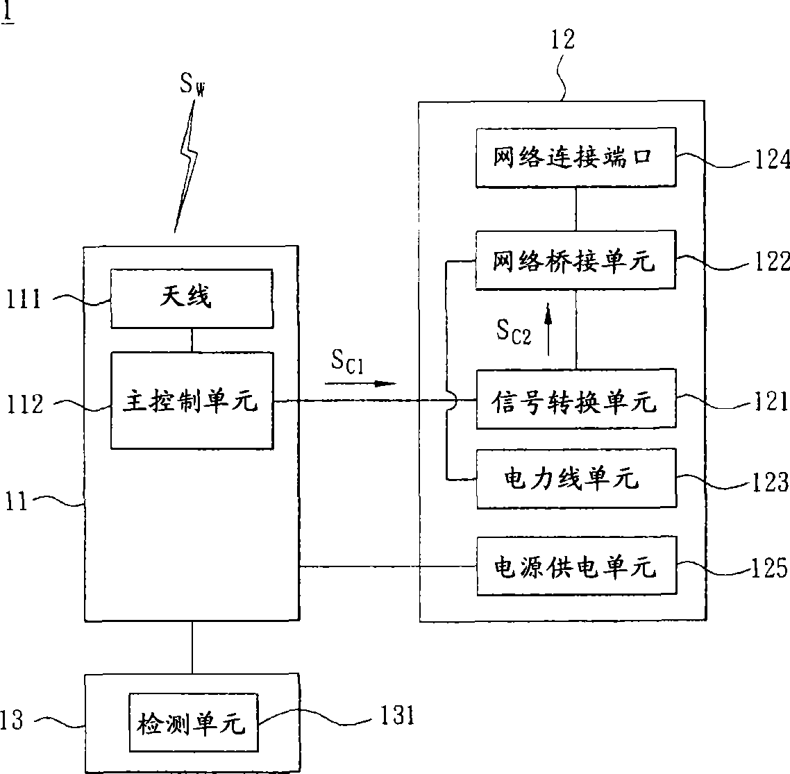
[0024] Please refer to figure 1 , a power network bridge device 1 according to a preferred embodiment of the present invention includes a wireless communication module 11 and a power network module 12 . The power network module 12 is electrically connected to the wireless communication module 11 .

[0025] The wireless communication module 11 includes an antenna 111 and a main control unit 112 . The antenna 111 is electrically connected to the main control unit 112 .

[0026] The wireless communication module 11 transmits or receives a wireless communication signal SW through the antenna 111 and transmits it to the main control unit 112 . In practice, the antenna 111 is an internal antenna or an external antenna, and the wireless communication signal SW can be an electromagnetic wave signal.

[0027] In addition...


PUM


Abstract

The present invention provides a power supply network bridge device comprising a radio communication module and a power supply network module. The radio communication module interconverts a first communication signal and a radio communication signal, and transmits or receives the radio communication signal. The power supply network module is connected with the radio communication module and a power line respectively, and the power supply network module interconverts the first communication signal and the power line signal which is transmitted by the power line.

Description

technical field [0001] The present invention relates to a bridging device, in particular to a power network bridging device. Background technique [0002] With the advancement of science and technology, various wireless transmission technologies have been continuously developed. In terms of short-distance wireless transmission technology, it includes bluetooth transmission technology and ZigBee transmission technology. Because ZigBee transmission technology not only has low power and can transmit text and pictures, ZigBee transmission technology also includes Advanced Encryption Standard (AES) to improve the security of wireless transmission time, making ZigBee transmission technology one of the research focuses in recent years . [0003] However, if the ZigBee transmission technology is applied to a large space (such as a wide house or a high-rise building across floors), since the ZigBee transmission technology is a short-distance wireless transmission technology, it is ...

Claims


Application Information

Patent Timeline
IPC IPC(8): H04B5/00H04B3/54
Inventor 邱志鸿林奇樑
Owner DELTA ELECTRONICS INC
Why Eureka
Try Eureka