Wall and column underpinning method

A column underpinning and wall technology, applied in building maintenance, construction, building construction, etc., can solve problems such as the height of columns and beams

Active Publication Date: 2009-05-13
上海天演建筑物移位工程股份有限公司
View PDF0 Cites 25 Cited by
  • Summary
  • Abstract
  • Description
  • Claims
  • Application Information

AI Technical Summary

Problems solved by technology

[0005] The disadvantage of this underpinning method is that it is not suitable for underpinning columns with heavy loads, because when the columns are heavy, the friction coefficient between the columns and the beams with the columns is fixed, and the beams with the columns will be very high.

Method used


Image

  • Wall and column underpinning method
  • Wall and column underpinning method
  • Wall and column underpinning method

Examples


Embodiment 1

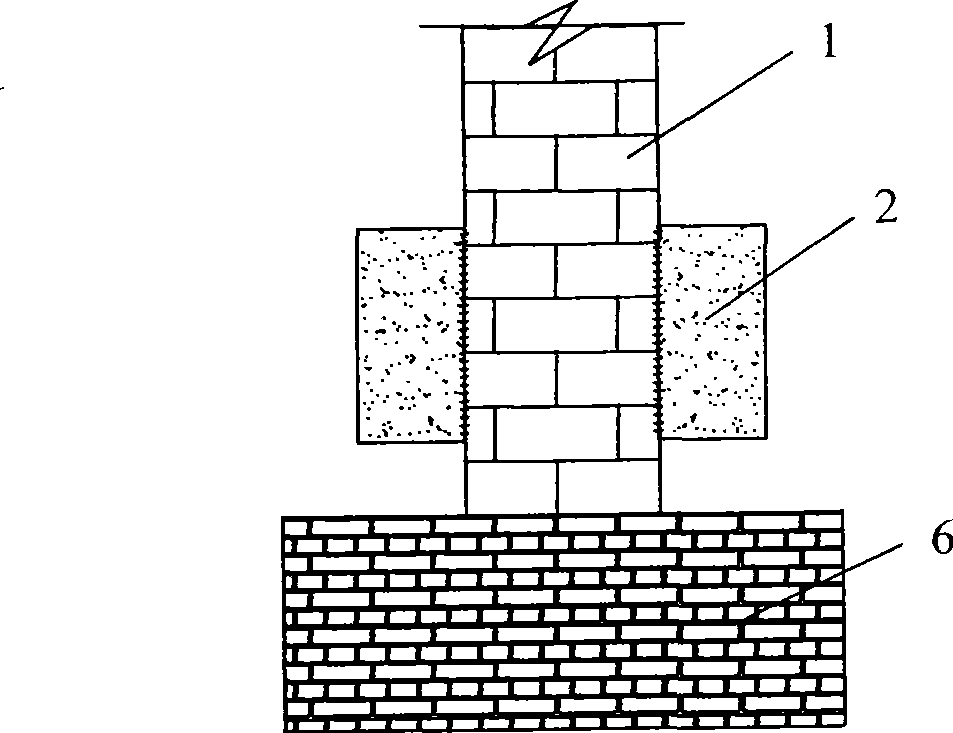
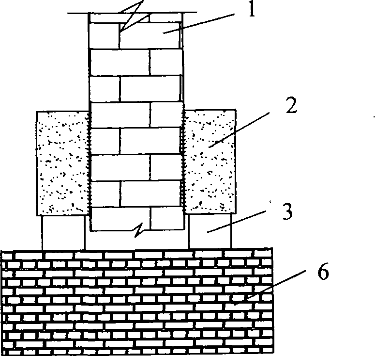
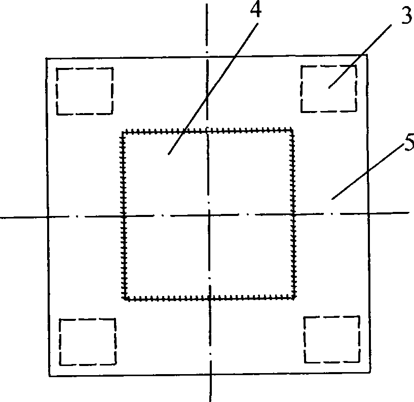
[0034] Such as Figure 7 , Figure 8 As shown, a reinforced concrete column-holding beam 5 is poured around the column 4, and the column and the reinforced concrete column-holding beam 5 are connected by an interface agent (the surface of the column can also be chiseled or not). The prestressed tendons 7 are worn to apply normal stress to the reinforced concrete column-hugging beam 5 . When the underpinning of the column 1 is cut off, the force of the column 4 is transmitted to the underpinning foundation 6 through the reinforced concrete column-holding beam 5 and the displacement device 3 . In the process of transferring the load from the column 4 to the reinforced concrete column-wrapped beam 5, the force is transmitted between the column 4 and the reinforced concrete column-wrapped beam 5 through the friction force between them and the normal stress friction force exerted by the prestressed tendon 7 on the column.

[0035] The advantages of the method described in this em...

Embodiment 2

[0037] Such as Figure 9 and Figure 10 As shown, a reinforced concrete column-holding beam 5 is poured around the bottom of the column 4, and the connection between the column 1 and the cast reinforced concrete column-holding beam 5 is connected by chiseling and interface agent; , and then jack unloading devices 8 are set on both sides of the upper column-holding beam 5 . The jack unloading device 8 is composed of an unloading jack 81 and an unloading column 82 .

[0038] When the underpinning of the column 1 is cut off, the force of the column 1 is transmitted to the underpinning foundation 6 through the column-holding beam 5 and the displacement device 3 . During the process of the column load being transferred to the column-holding beam, the column and the column-holding beam transmit force through the friction force between them and the normal stress friction force exerted by the jack unloading device on the column.

[0039] Similarly, this embodiment also has the adva...


PUM


Abstract

The invention relates to a method for underpinning a wall body and a pillar, wherein the method for underpinning the wall body comprises the following steps: firstly, an underpinning foundation is constructed; then a wall clamping beam is used to firmly clamp the wall body from both sides of the wall body, a shifting device is arranged under the wall clamping beam; and finally the wall body is cut to ensure that the force from a building is transferred to the wall clamping beam through the wall body, then the wall clamping beam transfers the force to the underpinning foundation through the shifting device, and a positive stress friction force is also applied between the wall clamping beam and the wall body. The method for underpinning the pillar comprises the following steps: firstly, the underpinning foundation is constructed; then a pillar surrounding beam is used to firmly clamp the pillar, a shifting device is arranged under the pillar surrounding beam; and finally the pillar is cut to ensure that the force from the building is transferred to the pillar surrounding beam through the pillar, then the pillar surrounding beam transfers the force to the underpinning foundation through the shifting device, and the positive stress friction force is also applied between the wall clamping beam and the pillar. The method for underpinning the wall body and the pillar has the advantage of adapting to wall bodies and pillars with heavy underpinning loads.

Description

technical field [0001] The invention relates to the overall displacement technology of a building, in particular to a method for supporting walls and columns in the overall displacement of a building. Background technique [0002] Before the overall movement of the building, it is necessary to underpin the upper part of the structure or the entire upper part of the foundation to the foundation for translation and jacking, and then use hydraulic equipment to translate and jack up to the designated position. Building underpinning is the core and key of moving technology. According to its load-bearing mode, there are mainly three kinds of underpinnings: wall underpinning, column underpinning and overall underpinning above the foundation. [0003] At present, the commonly used wall underpinning method at home and abroad: reinforced concrete and wall sandwich wall underpinning is to underpin the way of pouring reinforced concrete sandwich wall beams on both sides of the wall, su...

Claims


Application Information

Patent Timeline
Patent Type & Authority Applications(China)
IPC IPC(8): E04G23/06
Inventor 蒋岩峰林其荃蓝戊已赵殿峰李文亮徐福俊
Owner 上海天演建筑物移位工程股份有限公司
Why Eureka
Try Eureka