Distance measuring method and distance measuring element for detecting the spatial dimension of a target

A distance measuring method and a technology of a range finder, which are applied in the field of range finders and can solve problems such as parallel measurement of multiple sensors

Inactive Publication Date: 2009-06-03
LEICA GEOSYSTEMS AG
View PDF4 Cites 62 Cited by
  • Summary
  • Abstract
  • Description
  • Claims
  • Application Information

AI Technical Summary

Problems solved by technology

[0018] This method is not suitable for parallel measurements with several sensors, since in practice the requirement that the signal scattered back during the rough measurement be clearly distinguishable from noise can only be achieved with large pulse energies and therefore very complex light sources

Method used


Image

  • Distance measuring method and distance measuring element for detecting the spatial dimension of a target
  • Distance measuring method and distance measuring element for detecting the spatial dimension of a target
  • Distance measuring method and distance measuring element for detecting the spatial dimension of a target

Examples


Embodiment Construction

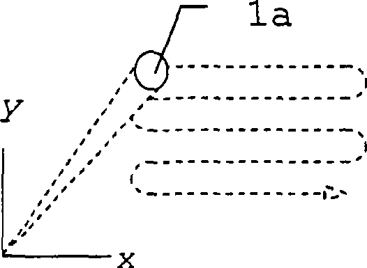
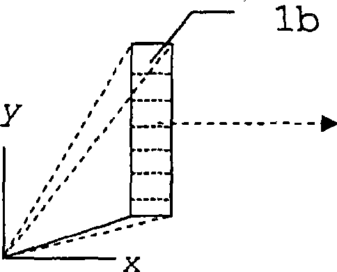
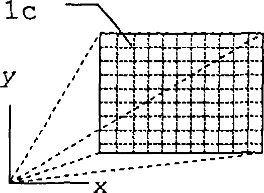
[0048] Figure 1a to Figure 1c A prior art method for determining the spatial dimension or shape of an object is explained. In order to scan the surface of an object, multiple light paths to many different points of the surface must be implemented.

[0049] like Figure 1a As shown, this can be achieved by a scanning movement of a single beam path with the aperture 1a, which in each case detects only a single point simultaneously. Objects are overwritten entirely sequentially. For this purpose, a light signal, generated for example by a laser, is directed onto the object via a scanning mechanism and is suitably shaped by the transmitter optics. A part of the light reflected by the object is received through the aperture 1a of the receiving optical system and guided to the optical sensor of the measuring system. Based on the signal transit time from the light source of the measurement system to the object and back to the sensor, the distance of each measured point can be der...


PUM


Abstract

A distance measuring method for detecting the spatial dimension of at least one target by at least one emission of a multiplicity of light pulses, in particular laser light, towards the target, detecting the light pulse scattered back by the target by means of a multiplicity of distance measuring pixels and eliminating the distance to the target for each pixel, wherein each light pulse can be detected within a measuring interval Ti comprising at least two, in particular equally long, part-intervals Ti,j, characterized in that the detection comprises a detection step carried out with at least one repetition in at least two stages, the measuring interval Ti is shortened from stage to stage.

Description

technical field [0001] The invention relates to a distance measuring method for determining the spatial dimension of at least one object according to the preamble of claim 1 and a corresponding distance measuring device according to the preamble of claim 8 . Background technique [0002] Various measurement devices have existed since ancient times for recording properties of defined points in the measurement environment, especially defined points with spatially referenced data. The measurement equipment is recorded as standard spatial data along with the position of any reference points that exist and the direction, distance and angle to the target and the measured point. [0003] A well-known example of such a measuring device is a theodolite. In the two-dimensional representation of the optical image, it is possible to specify points at which measurements are made (ie distances and / or angles are determined). On the basis of this image, objects can be identified and track...

Claims


Application Information

Patent Timeline
Patent Type & Authority Applications(China)
IPC IPC(8): G01S17/89G01S17/10G01S7/487G01S7/4865G01S17/18G01S17/894
CPCG01S17/89G01S7/4865G01S17/107G01S7/487G01S7/497G01S17/18G01S17/894
Inventor 马塞尔·罗纳贝亚特·埃比舍尔托马斯·延森克努特·西尔克斯
Owner LEICA GEOSYSTEMS AG
Why Eureka
Try Eureka