Electromagnetic vortex imaging method under single-antenna receiving condition

An imaging method and single-antenna technology, applied in radio wave measurement system, radio wave reflection/reradiation, utilization of reradiation, etc., can solve the problem of complex implementation, the impact of time synchronization accuracy on imaging quality, and the inability to distinguish target azimuth, etc. problem, to achieve the effect that the receiving process is simple and easy to implement

Active Publication Date: 2017-06-23
NAT UNIV OF DEFENSE TECH
View PDF2 Cites 34 Cited by
  • Summary
  • Abstract
  • Description
  • Claims
  • Application Information

AI Technical Summary

Problems solved by technology

In the case of array reception, each antenna needs to receive the echo signal at the same time, and the time synchronization accuracy between the antennas has a great impact on the imaging quality, which is more complicated to implement
When the target elevation angle is small, direct imaging processing of the echoes received by a single antenna cannot resolve the target azimuth

Method used


Image

  • Electromagnetic vortex imaging method under single-antenna receiving condition
  • Electromagnetic vortex imaging method under single-antenna receiving condition
  • Electromagnetic vortex imaging method under single-antenna receiving condition

Examples


Embodiment Construction

[0018] The present invention will be described in detail below in combination with specific embodiments.

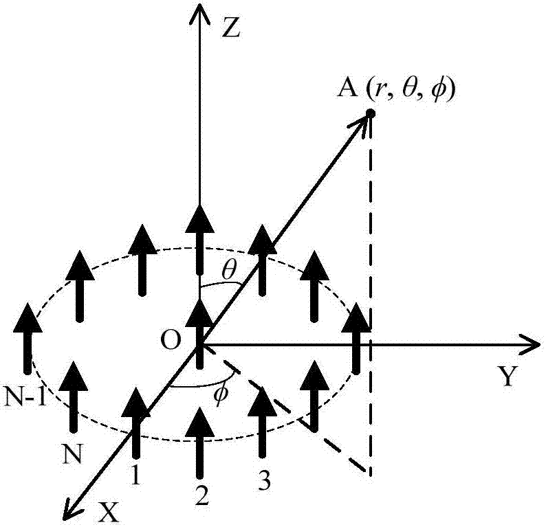
[0019] In the first step, N identical antennas are arranged at equal intervals on a circle with a radius R to form a transmitting array. The number N of antennas and the radius R of the array are set according to the imaging requirements. Generally, the larger the number N of antennas, the more types of orbital angular momentum modes carried by the electromagnetic vortex generated by the transmitting array, and the smaller the radius R of the array, the greater the electromagnetic vortex generated. The side lobes are less. Taking the center of the transmitting array as the coordinate origin, place the transmitting array in the XOY plane, and establish the radar observation space coordinate system XYZ, as shown in figure 2 shown. figure 2 In , each short arrow represents an antenna, N transmitting antennas are placed on the circle indicated by the dotted line, and a re...


PUM


Abstract

The invention provides an electromagnetic vortex imaging method under a single-antenna receiving condition. The technical scheme comprises the following steps: S1, N identical antennas are evenly distributed on a circumference to form a transmitting array; S2, electromagnetic vortexes of different frequencies and different orbital angular momentum modes are transmitted in turn using the transmitting array, and a single antenna in the center of the transmitting array receives each target echo, wherein the amplitude and phase information of the target echo received constitute frequency-orbital angular momentum mode two-dimensional echo data; S3, phase compensation is made for the received two-dimensional echo data according to the prior information of the parameters of the transmitting array and the elevation angle of a target to get preprocessed two-dimensional echo data; and S4, two-dimensional Fourier transform is carried out on the preprocessed two-dimensional echo data to get a distance-azimuth two-dimensional image of the target. The receiving process is simple. The method is easy to implement. Reference can be provided for the development of target recognition and new-system radar imaging technologies.

Description

technical field [0001] The present invention relates to the technical field of microwave imaging, in particular to the electromagnetic vortex imaging technology, and more specifically to the electromagnetic vortex imaging by using a single antenna to receive echoes. Background technique [0002] Radar imaging technology is not limited by natural conditions, and has very important applications in the fields of space target monitoring, remote sensing mapping, and ocean observation. Most of the existing high-resolution imaging radars are based on the range-Doppler principle, and the azimuth resolution depends on the viewing angle range of the radar. In practical applications, it is sometimes necessary to conduct long-term uninterrupted stationary observations of a key area. Under such staring observation conditions, it is difficult to obtain high azimuth resolution by imaging techniques under the range-Doppler framework. [0003] Orbital angular momentum is an important physic...

Claims


Application Information

Patent Timeline
Patent Type & Authority Applications(China)
IPC IPC(8): G01S13/89
CPCG01S13/89
Inventor 秦玉亮程永强袁铁柱王宏强范波李彦鹏
Owner NAT UNIV OF DEFENSE TECH
Why Eureka
Try Eureka