Display device, computer terminal, and antenna

a display device and computer terminal technology, applied in the direction of differentially interacting antenna combinations, electrical apparatus casings/cabinets/drawers, identification means, etc., can solve the problems of time and labor, internal or embedded antennas generally not performing as well as external antennas, and the ground capacity of antennas can be increased, and the effect of excellent durability

a display device and computer terminal technology, applied in the direction of differentially interacting antenna combinations, electrical apparatus casings/cabinets/drawers, identification means, etc., can solve the problems of time and labor, internal or embedded antennas generally not performing as well as external antennas, and the ground capacity of antennas can be increased, and the effect of excellent durability

US6853336B2Inactive Publication Date: 2005-02-08LENOVO PC INT

Image

  • Display device, computer terminal, and antenna
  • Display device, computer terminal, and antenna
  • Display device, computer terminal, and antenna

Examples


Embodiment Construction

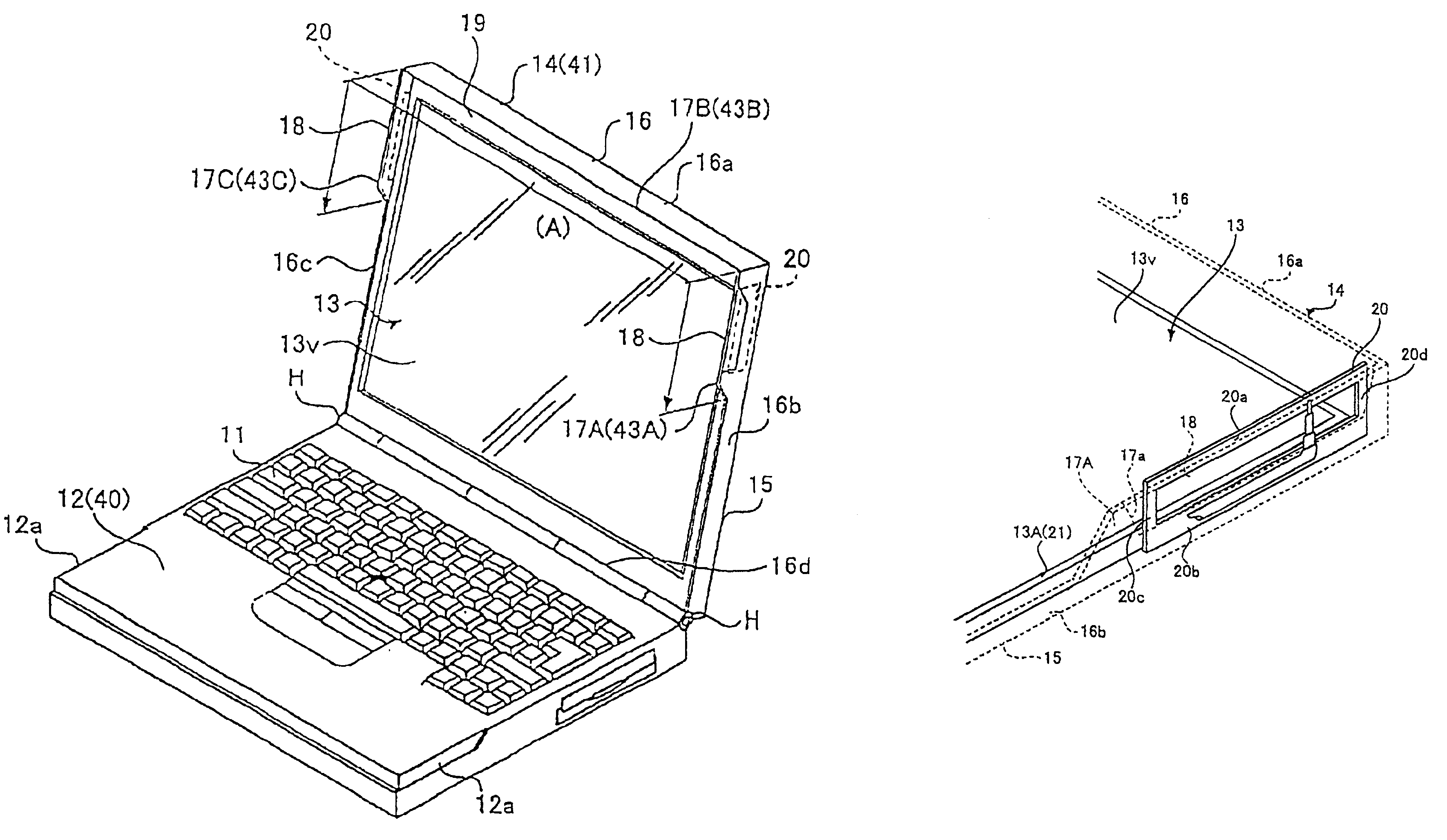
According to an embodiment of the present invention, embedded antennas are disposed on an edge of a laptop display, the metal rims that supports the display, and / or in an RF shielding foil backing the display. Many antenna types, such as chip antennas, slot antennas, inverted-F antennas and notch antennas, are applicable in this design. The advantages of this design include: smaller antenna size, inexpensive to manufacture, minimum effects on industrial design, and reliable performance.

FIGS. 3A-3F show illustrative configurations of a computer terminal according to an embodiment of the present invention. As shown in FIG. 3A, the notebook computer terminal includes a base housing (second housing) 12 with a keyboard 11 and a display panel housing (housing, first housing, second ground) 14 with a display panel 13. The base housing 12 and the display panel housing 14 are rotatably connected to each other through a hinge unit H. It should be appreciated that the base housing 12 and the d...


PUM


Abstract

In a notebook type computer terminal, a plate type slot antenna is provided between a display panel and a surrounding wall of a display panel housing so that a radiator portion thereof is projecting from a frame of the display panel and a stay, which are made of conductive material by a length more than a predetermined dimension S. A ground portion of the antenna is connected not only to a ground of a radio transceiver unit but also to the display panel housing made of conductive material through the stay.

Description

BACKGROUND OF THE INVENTION1. Field of the InventionThe present invention relates to a display device, a computer terminal, and an antenna which are capable of wireless data communication.2. Discussion of the Prior ArtTypically, a wired cable is used by a laptop to communicate with another processing device such as another laptop, desktop, server, or printer. To communicate without a wired connection, an antenna is needed. FIG. 1 shows two possibilities of outside antennas.Antennas can be located at the top of a laptop display 1 for better RF clearance, or just outside (dash line for antenna) of a PCMCIA card 2. Usually, the laptop will have an optimum wireless performance if the antenna is mounted on the top of the display 1. However, an external antenna will generally be more expensive and susceptible to damage than an internal antenna. Alternatively, an internal or embedded antenna generally will not perform as well as an external antenna.The commonly used method to improve the p...

Claims


Application Information

Patent Timeline
08 Feb 2005
Publication
US6853336B2
IPC
H01Q1/22; H01Q9/04; H01Q21/28; H01Q13/10; H01Q21/00; H01Q21/29; G09F9/00; G06F1/16
CPC
H01Q1/22; H01Q1/2266; H01Q9/0421; H01Q21/29; H01Q13/106; H01Q21/28; H01Q9/42; G06F1/1698
Inventors
ASANO, TAKESHI; FLINT, EPHRAIM B.