Instant-heating type drinking machine hydrothermal system

A water dispenser and instant heating technology, applied in water heaters, fluid heaters, beverage preparation devices, etc., can solve problems affecting human health, power waste, aging, etc.

Inactive Publication Date: 2009-06-24
余志刚
0 Cites 7 Cited by

AI-Extracted Technical Summary

Problems solved by technology

In the standby state of the water dispenser, the hot pot is always in the cycle of repeated heating, and the waste of power is ...

Method used

When solenoid valve thermostat 4 reaches set temperature, solenoid valve 6 starts work, and solenoid valve thermostat 4 can reset automatically. When the anti-dry thermostat 5 reaches the set temperature, it will automatically power off, and the heater 8 connected to the circuit will be powered off to ensure safe use. The anti-dry thermostat 5 needs to be manually reset. The power of the heater 8 is controlled within 3000W, further guaranteeing the safety of use. The transformer 12 reduces the 220V mains power to the required low voltage, generally to 6-12v low voltage. The function of...

Abstract

An instant heating drinking machine water heating system pertains to the field of drinking machine technology, which is characterized in that one path of the water inlet pipe is connected to the water inlet pipe of a water tank at the bottom of the cold water tank through a three-way pipe, while the other path is connected to the pipes at the bottom of the vertically arranged heating water pipes, heaters are vertically arranged in the heating water pipes, the upper side of the heating water pipes are connected to the hot water faucet pipes, exhausting pipes are connected to the top of the heating water pipes, the exhausting pipes connects and extend into a cold water tank, the export position of the exhausting pipe is located in an upper cavity of the cold water tank, the cold water tank is connected to cold water tap pipes through a water tank water outlet provide4d on the lateral wall, and the position of the water outlet of the water tank is higher than that of the water inlet of the water tank. The instant heating drinking machine water heating system, after fetching a first cup of hot water, only need a few seconds to get a second cup without waiting, and can fetch discretional cup of hot-water until the water in the barrel water or bagging water is over. The drinking machine adopting the system saves more than 80% of electricity compared with the traditional drinking machines.

Application Domain

Beverage vesselsWater heaters

Technology Topic

Water pipeElectricity +4

Image

  • Instant-heating type drinking machine hydrothermal system
  • Instant-heating type drinking machine hydrothermal system
  • Instant-heating type drinking machine hydrothermal system

Examples

  • Experimental program(1)

Example Embodiment

[0019] The present invention will be further described below in conjunction with the accompanying drawings of the specification.
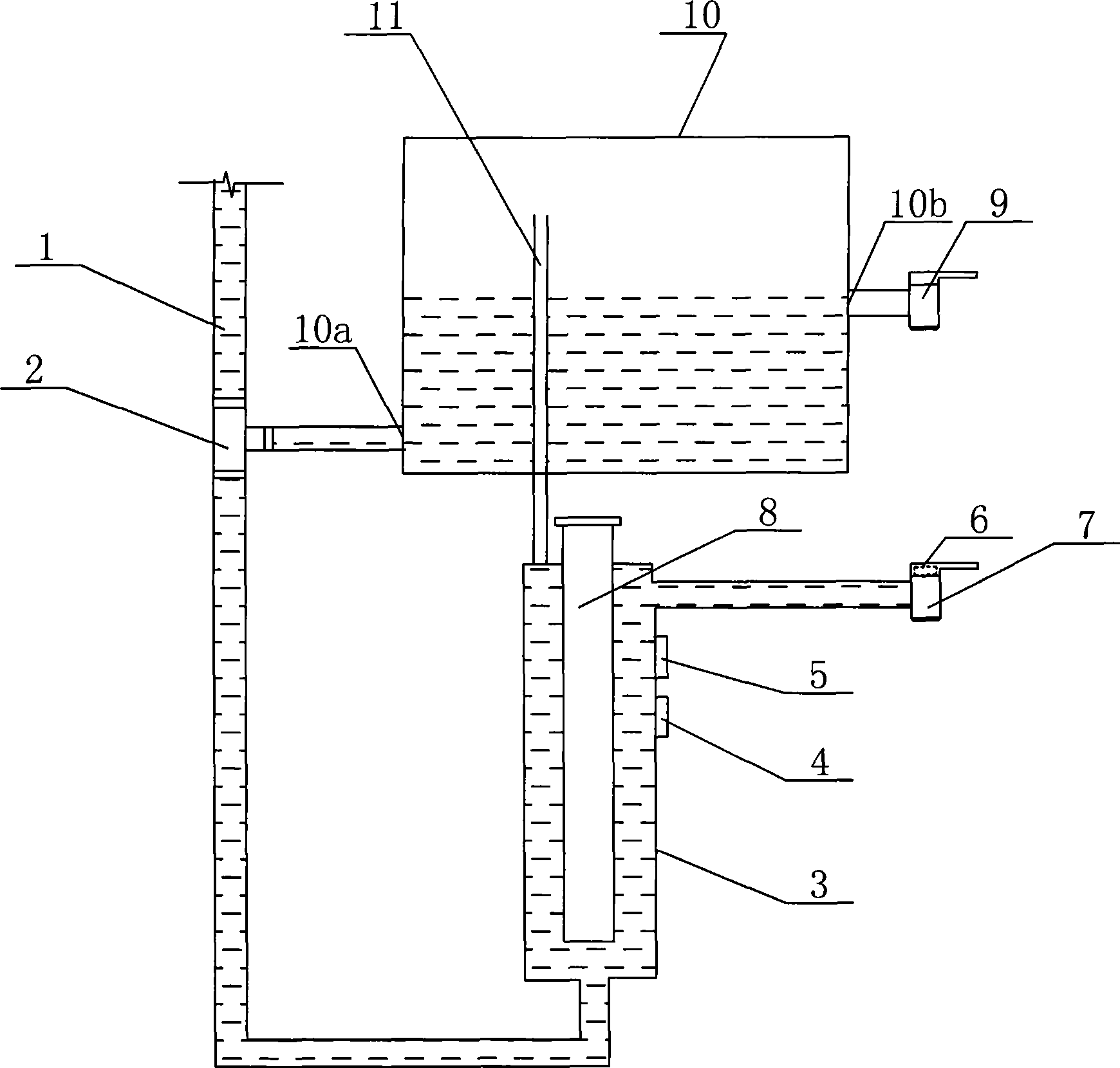
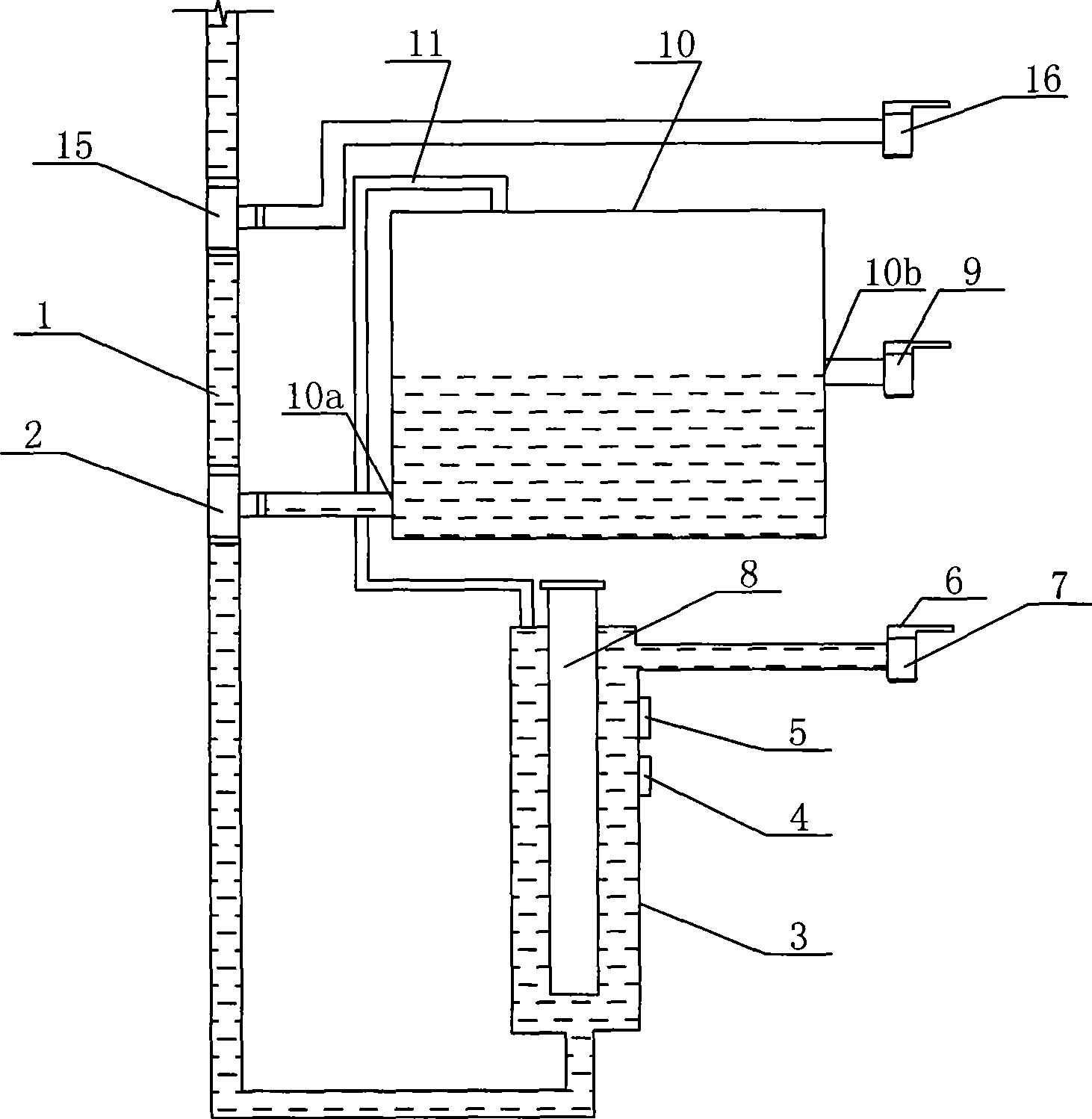
[0020] As shown in the figure, the water heating system of the instant water dispenser includes a water inlet pipe 1 connected to the outlet of bottled water or bagged water. The water inlet pipe 1 is connected to the water tank water inlet 10a at the bottom of the cold water tank 10 through the tee pipe 2, and the other is connected to the bottom pipe of the heating water pipe 3. The heating water pipe 3 is installed vertically, and the heater 8 is installed vertically in the heating water pipe 3. The upper part of the heating water pipe 3 is connected to the hot water faucet 7, and an exhaust pipe 11 is connected to the top of the heating water pipe 3. The exhaust pipe 11 is connected to extend into the cold water tank 10, and the outlet position of the exhaust pipe 11 is in the upper cavity of the cold water tank 10. 10 is connected to the cold water faucet 9 through the water tank outlet 10b provided on the side wall. The water tank outlet 10b is higher than the water tank inlet 10a, and the water tank outlet 10b is preferably arranged at half of the side wall of the cold water tank 10. The exhaust pipe 11 can extend from the bottom of the cold water tank 10 into its upper cavity, and the outlet position of the exhaust pipe 11 is higher than the water tank outlet 10b. The exhaust pipe 11 may also be connected to an opening provided on the upper part of the cold water tank 10 and extend into the upper cavity of the cold water tank 10 through the opening connection.
[0021] The net capacity of the heating water pipe 3 is 200ml-300ml, the power of the heater 8 is 2000w-3000w, and the capacity of the cold water tank 10 is 1000ml-1500ml. The net capacity of the heating water pipe 3 refers to the total capacity of the heating water pipe 3 minus the space occupied by the heater 8. It should be equal to the capacity of a glass of water, generally 200ml is better, when the net capacity of the heating water pipe 3 is 200ml Below, the capacity of the cold water tank 10 is preferably 1000ml, and the power of the heater 8 is 3000W. When the water outlet 10b of the water tank is arranged at one-half of the side wall of the cold water tank 10, the volume of water and the volume of the cavity in the cold water tank 10 are each 500 ml. Through the standard setting of various parameters, all the steam generated by the heating water pipe 3 during heating can be discharged into the cold water tank 10 and be condensed and absorbed, so that the hot water flowing from the hot water faucet 7 meets the drinking water temperature standard of the water dispenser. If the volume of the cold water tank 10 is too small, the steam generated in the heating water pipe 3 cannot be discharged into the cold water tank 10, causing the inside of the heating water pipe 3 to vaporize and hot water cannot flow out.
[0022] The wall of the heating water pipe 3 is matched with an anti-dry-burning thermostat 5, and the anti-dry-burning thermostat 5 is connected to the heater 8 and the power source 14. The hot water faucet 7 is provided with a solenoid valve 6 and the heating pipe 3 is provided with a solenoid valve thermostat 4 correspondingly. The solenoid valve 6 and the solenoid valve thermostat 4 are connected to the transformer 12, the bridge rectifier circuit 13, and the power source 14.
[0023] The water coming out of the cold water tank 10 has a certain string temperature, and the lower the water tank outlet 10b, the smaller the impact. To this end, a three-way joint 15 can be connected to the upper part of the water inlet pipe 1. The three-way joint 15 is connected to the second cold water tap 16 through a pipe, and the cold water coming out of the second cold water tap 16 will not have a cross-temperature phenomenon.
[0024] When the solenoid valve thermostat 4 reaches the set temperature, the solenoid valve 6 opens to work, and the solenoid valve thermostat 4 can automatically reset. When the anti-dry-burning thermostat 5 reaches the set temperature, it will automatically power off, and the heater 8 connected to its circuit will be powered off to ensure safe use. The anti-dry-burning thermostat 5 needs to be reset manually. The power of the heater 8 is controlled within 3000W to further ensure the safety of use. The transformer 12 reduces the 220V city power to the required low voltage, generally to 6-12v low voltage. The function of the bridge rectifier circuit 13 is to convert alternating current into direct current, and the specific structure is known in the prior art. You must wait for 5-30 seconds each time you receive the first glass of water. The length of the waiting time is determined by the ambient temperature and the temperature of the cold water when the water dispenser is used. The higher the ambient temperature and cold water temperature, the shorter the waiting time. After the first cup of boiling water flows out, if you take the second cup or any cup, you don’t need to wait, it’s ready to use.
[0025] The cold water faucet 9 serves as the initial air discharge port. When using it for the first time, you should open the cold water faucet 9 first, and then close it after the water flows out. At this time, the water level in the cold water tank 10 is at the same height as the water outlet 10b of the water tank; , To take cold water, turn on the cold water faucet 9, and to take hot water, turn on the power supply 14 by turning on the power switch. The heater 8 starts to work. When the water temperature in the heating pipe 3 reaches the set temperature, the solenoid valve 6 opens, and the hot water Outflow; the steam generated in the heating water pipe 3 enters the upper cavity of the cold water tank 10 from the exhaust pipe 11, and is condensed and recovered into the cold water tank 10; the power supply 14 is turned off, the heater 8 stops working, and the solenoid valve 6 is closed. Every time you take the first cup of hot water, you need to wait a few seconds. From the second cup, you don’t need to wait. You can take any cup of hot water until the bottled water or the water in the bag is taken.
[0026] The present invention can continuously flow cold water at 15°C into the heating water pipe 3 at a speed of 10 ml per second, and then flow out from the hot water tap 7 after being heated to 90°C. According to the law of conservation of energy, the following calculations can be verified:
[0027] 1. The heat required to burn 200ml of drinking water from 15°C to 90°C is 200ml×4.2×(90°C-15°C)=63000 joules.
[0028] 2. The heat required for every 1 degree increase in the temperature of 200ml drinking water is 63000÷75=840 joules.
[0029] 3. When the hot water faucet 7 is turned off, heating for 10 seconds, the heat that can be obtained by heating 200ml of drinking water in the water pipe 3 is:
[0030] 3000ml×10 seconds=30000 joules, these heat can raise the temperature of the water in the heating water pipe 3 to 15+(30000÷840)=51 degrees.
[0031] 4. When the temperature of the water in the heating water pipe 3 rises to 51 degrees, the solenoid valve 6 of the hot water faucet 7 is opened through the solenoid valve thermostat 4. When 200ml of drinking water in the heating water pipe 3 is heated from the hot water faucet 7 at a rate of 10 ml per second In the process of all outflow, the heat obtained is:
[0032] 3000W×1 second÷200ml×10ml
[0033] +3000W×2sec÷200ml×10ml
[0034] +3000W×3sec÷200ml×10ml
[0035]...
[0036] +3000W×20 seconds÷200ml×10ml
[0037]=3000W×(1+2+3+……+20)÷200ml×10ml
[0038] = 31500 joules, these heat can heat 200ml of 51 degrees water to 51+(31500÷840)=51+37.5=88.5 degrees.
[0039] 5. The time required to boil the first cup of 200ml of water at 15°C to 88.5°C is 10 seconds + 20 seconds = 30 seconds.
[0040] 6. While the first cup of 200ml drinking water flows out from the heating pipe 3 at 10ml per second, the second 200ml drinking water flows into the heating pipe 3 at the same speed, and the following heat is obtained in the process:
[0041] 3000W×(1+2+……+20)×200ml÷10ml=31500 joules, while the second 200ml drinking water flows out from the heating pipe 3 at a rate of 10ml per second, the third 200ml drinking water also It flows into the heating water pipe 3 at the same speed. During this process, the second 200ml and the third 200ml drinking water respectively get 31500 joules of heat, and each 200ml drinking water flows in and out at 10ml per second. The total heat obtained in the process of heating the water pipe 3 is 31500×2=63000 joules, which can increase the temperature of 200ml drinking water from 15 degrees to 15+(63000÷840)=90 degrees.
[0042] In summary, the present invention better achieves the goal of ready-to-use and burns, with ingenious design, unique concept, stable performance, and convenient use. The water dispenser using the system can save more than 80% of electricity compared with traditional water dispensers.

PUM

no PUM

Description & Claims & Application Information

We can also present the details of the Description, Claims and Application information to help users get a comprehensive understanding of the technical details of the patent, such as background art, summary of invention, brief description of drawings, description of embodiments, and other original content. On the other hand, users can also determine the specific scope of protection of the technology through the list of claims; as well as understand the changes in the life cycle of the technology with the presentation of the patent timeline. Login to view more.
Why Eureka
Try Eureka