Flow limitation method and apparatus

A technology of flow limitation and flow, which is applied in the field of communication, and can solve problems such as inconvenient flow management

Inactive Publication Date: 2009-07-08
HUAWEI TECH CO LTD
View PDF0 Cites 8 Cited by
  • Summary
  • Abstract
  • Description
  • Claims
  • Application Information

AI Technical Summary

Problems solved by technology

[0005] Embodiments of the present invention provide a traffic limiting method and device to solve the problem of inconvenient traffic management in the main tunnel to the sub-tunnel

Method used


Image

  • Flow limitation method and apparatus
  • Flow limitation method and apparatus
  • Flow limitation method and apparatus

Examples


Embodiment Construction

[0020] The technical solutions of the present invention will be described in further detail below with reference to the accompanying drawings and embodiments.

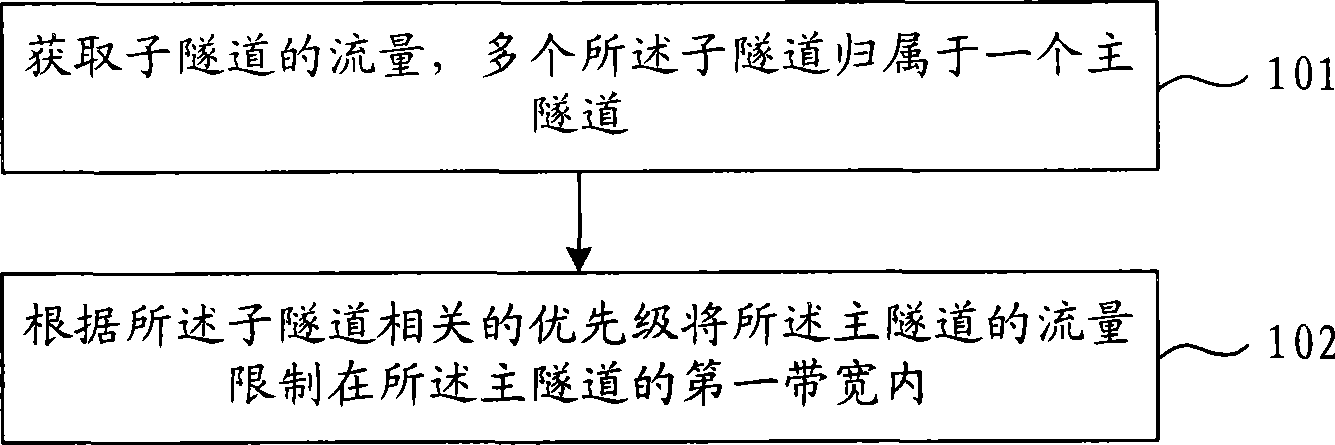
[0021] figure 1 It is a flowchart of an embodiment of the flow limiting method of the present invention. like figure 1 As shown, the traffic restriction method includes the following steps:

[0022] Step 101. Obtain traffic of sub-tunnels, where multiple sub-tunnels belong to one main tunnel.

[0023] In a communication network, a network device such as an NPE can detect each sub-tunnel, and obtain the traffic of each sub-tunnel, that is, the amount of data passing through the sub-tunnel per second. Before obtaining traffic, multiple sub-tunnels can be established according to different services, and the multiple sub-tunnels can be bundled into a main tunnel. The usual practice is to use the private network tunnel established between UPEs as a sub-tunnel, and connect the The established public network tunnel is use...


PUM


Abstract

The embodiment of the invention relates to a traffic limiting method and a device. The traffic limiting method comprises the following steps: acquiring the traffic of sub-tunnels, which belong to one main tunnel; and limiting the traffic of the main tunnel in a first bandwidth of the main tunnel according to the correlative priorities of the sub-tunnels, wherein, the traffic of the main tunnel is the traffic summation of all of the sub-tunnels; and the first bandwidth is the largest bandwidth of the main tunnel. In the embodiment, the main tunnel can achieve traffic limitation and management of the sub-tunnels according to the correlative priorities of the sub-tunnels, thereby ensuring successful transmission of traffic with higher priority.

Description

technical field [0001] The embodiments of the present invention relate to the technical field of communications, in particular to a flow limiting method and device. Background technique [0002] With the accelerated development of the network, the tunnel technology is more and more widely used. The traffic engineering (Traffic Engineering; TE) established by the edge nodes is aggregated at the core nodes of the network, so that the TE tunnels established by all edge nodes are managed by one main tunnel, which can simplify the session state of the core network and use TE fast rerouting (Fast Reroute; hereinafter referred to as: FRR) for protection. [0003] The existing tunnel bundling technology generally establishes two tunnels (TE1 and TE2) between user-end provider edge devices (User-end Provider Edge; hereinafter referred to as UPE), and between network-side edge devices (Network Provider Edge; hereinafter referred to as NPE). A tunnel (TE3) is established between them...

Claims


Application Information

Patent Timeline
IPC IPC(8): H04L12/56H04L12/46H04L12/811
Inventor 张永平
Owner HUAWEI TECH CO LTD
Why Eureka
Try Eureka