Solar energy heat collection system

A technology of solar heat collection and solar heat collector, which is applied in the field of solar heat collection system to achieve the effects of preventing dry burning, improving comfort and preventing water temperature from being too high

Inactive Publication Date: 2011-06-15
江苏联宇新能源科技有限公司
View PDF2 Cites 1 Cited by
  • Summary
  • Abstract
  • Description
  • Claims
  • Application Information

AI Technical Summary

Problems solved by technology

[0006] The technical problem to be solved by the present invention is to provide a solar heat collection system, which can still have a good heat collection effect in winter or in the case of insufficient sunlight for several consecutive days, so as to reduce the need for additional heating when using water

Method used


Image

  • Solar energy heat collection system
  • Solar energy heat collection system
  • Solar energy heat collection system

Examples


Embodiment 1

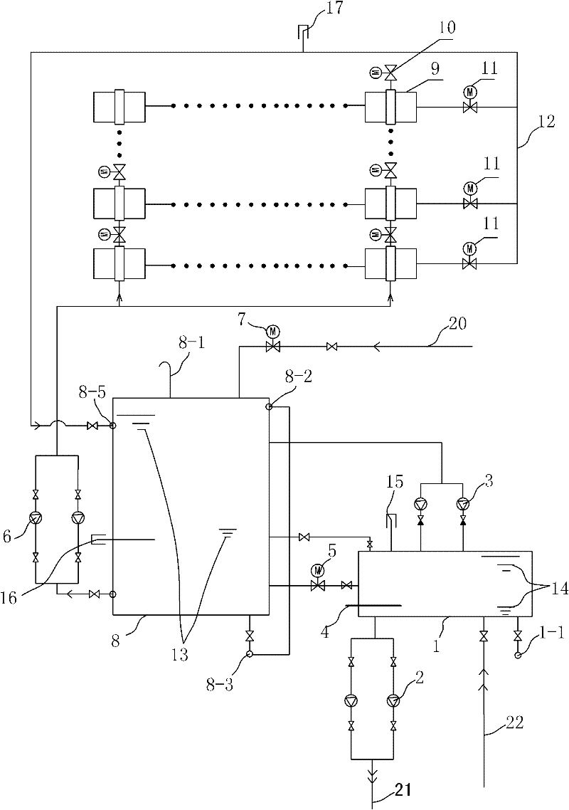
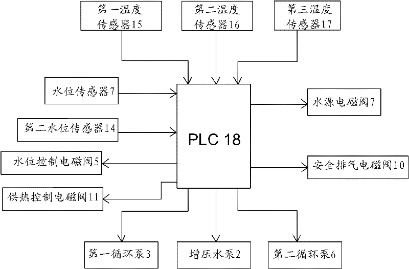
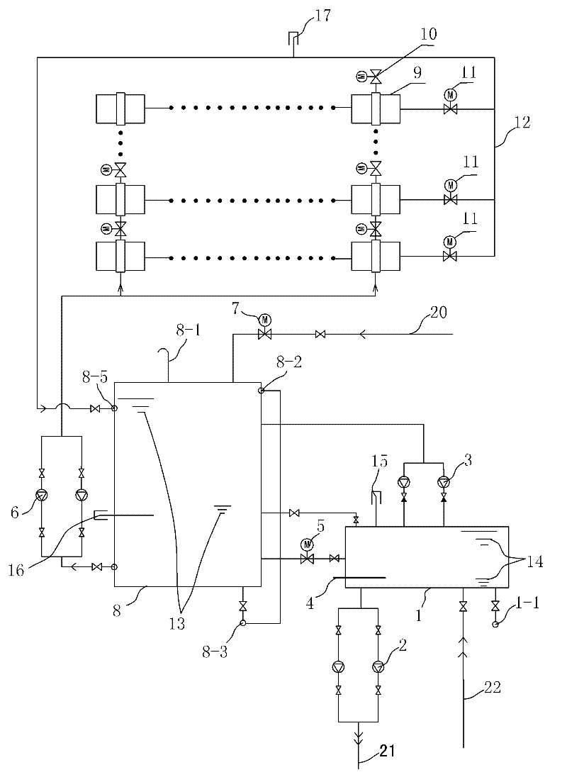
[0014] See Figure 1-2 , the solar heat collection system of the present embodiment includes: a solar heat collector 9, a water collection tank 8, a constant temperature water tank 1 and a program logic controller PLC18 connected successively through a circulation pipeline; In the same way, the tap water replenishment pipe 20 is provided with a water source solenoid valve 7, and a water level sensor 13 is provided in the water collecting tank 8; the water level sensor 13 and the water source solenoid valve 7 are connected with the PLC18; the PLC18 outputs the water level signal according to the water level sensor 13 Control the water source solenoid valve 7 to open or close to automatically replenish water to the hot water tank, realize regular and quantitative water supply, and control the water source solenoid valve to automatically replenish cold water by setting the time and the highest water level. It can also be intelligently set according to the actual situation to supp...


PUM


Abstract

The invention relates to a solar energy heat collection system which comprises a solar heat collector, a heat collection water tank, a constant-temperature water tank and a PLC. The heat collection waThe invention relates to a solar energy heat collection system which comprises a solar heat collector, a heat collection water tank, a constant-temperature water tank and a PLC. The heat collection water tank is communicated with a tap water replenishing pipe; a water source electromagnetic valve is arranged on the tap water replenishing pipe; a water level sensor is arranged in the heat collectioter tank is communicated with a tap water replenishing pipe; a water source electromagnetic valve is arranged on the tap water replenishing pipe; a water level sensor is arranged in the heat collection water tank; the PLC controls the opening and the closing of the water source electromagnetic valve through a water level signal output by the water level sensor so as to automatically replenish waten water tank; the PLC controls the opening and the closing of the water source electromagnetic valve through a water level signal output by the water level sensor so as to automatically replenish water for the heat collection water tank and realize quantificational water feeding in fixing time; water quantity in the heat collection water tank can be controlled according to actual condition, for exr for the heat collection water tank and realize quantificational water feeding in fixing time; water quantity in the heat collection water tank can be controlled according to actual condition, for example, in winder or under the condition that the sunlight is not sufficient for continuous several days, the water quantity in the heat collection water tank is controlled to be less to ensure that thample, in winder or under the condition that the sunlight is not sufficient for continuous several days, the water quantity in the heat collection water tank is controlled to be less to ensure that the water in the heat collection water tank keeps higher temperature, therefore, heating is not needed when water is used, and the energy-saving purpose is achieved. In high-temperature seasons, steam ie water in the heat collection water tank keeps higher temperature, therefore, heating is not needed when water is used, and the energy-saving purpose is achieved. In high-temperature seasons, steam is released through a safety exhaust valve, and the heat supply area of a heat collector array is controlled by a heat supply control valve, thereby the running stability and security of the system ares released through a safety exhaust valve, and the heat supply area of a heat collector array is controlled by a heat supply control valve, thereby the running stability and security of the system are ensured.ensured.

Description

technical field [0001] The invention relates to a solar heat collection system. Background technique [0002] With the increasing shortage of conventional energy supply, solar heat collection systems are gradually being popularized and applied. [0003] Chinese patent literature publication number CN1142594 discloses a solar heat collection system, including a pump, which pumps the water in the thermal insulation barrel into the heat collector to collect solar energy, and a temperature sensor is arranged on the heat collector The entrance of the collector, and a central processing unit connected to the temperature sensor to detect the temperature of the water pumped or stored in the collector, the central processing unit can preset an initial value of the temperature difference and the exposure of the collector Then, the temperature difference standard can be reduced and the exposure time of the collector can be increased according to the weather, so that the solar energy c...

Claims


Application Information

Patent Timeline
Patent Type & Authority Patents(China)
IPC IPC(8): F24J2/04F24J2/40F24J2/46F24J2/00G05D23/19G05B19/04
CPCY02E10/44
Inventor 史指风蒋红桥
Owner 江苏联宇新能源科技有限公司
Why Eureka
Try Eureka