

Fin, heat exchanger with fin and heat exchanger device
一种换热器、翅片的技术,应用在换热器装置领域,能够解决换热器性能下降、传热系数减小、外观差等问题,达到排列密度均匀、形状稳定、传热系数大的效果
- Summary
- Abstract
- Description
- Claims
- Application Information
AI Technical Summary
Problems solved by technology
Method used
Image

Examples
Embodiment Construction
[0037] Embodiments of the present invention are described in detail below, examples of which are shown in the drawings, wherein the same or similar reference numerals designate the same or similar elements, or elements having the same or similar functions, throughout. The embodiments described below by referring to the figures are exemplary only for explaining the present invention and should not be construed as limiting the present invention.
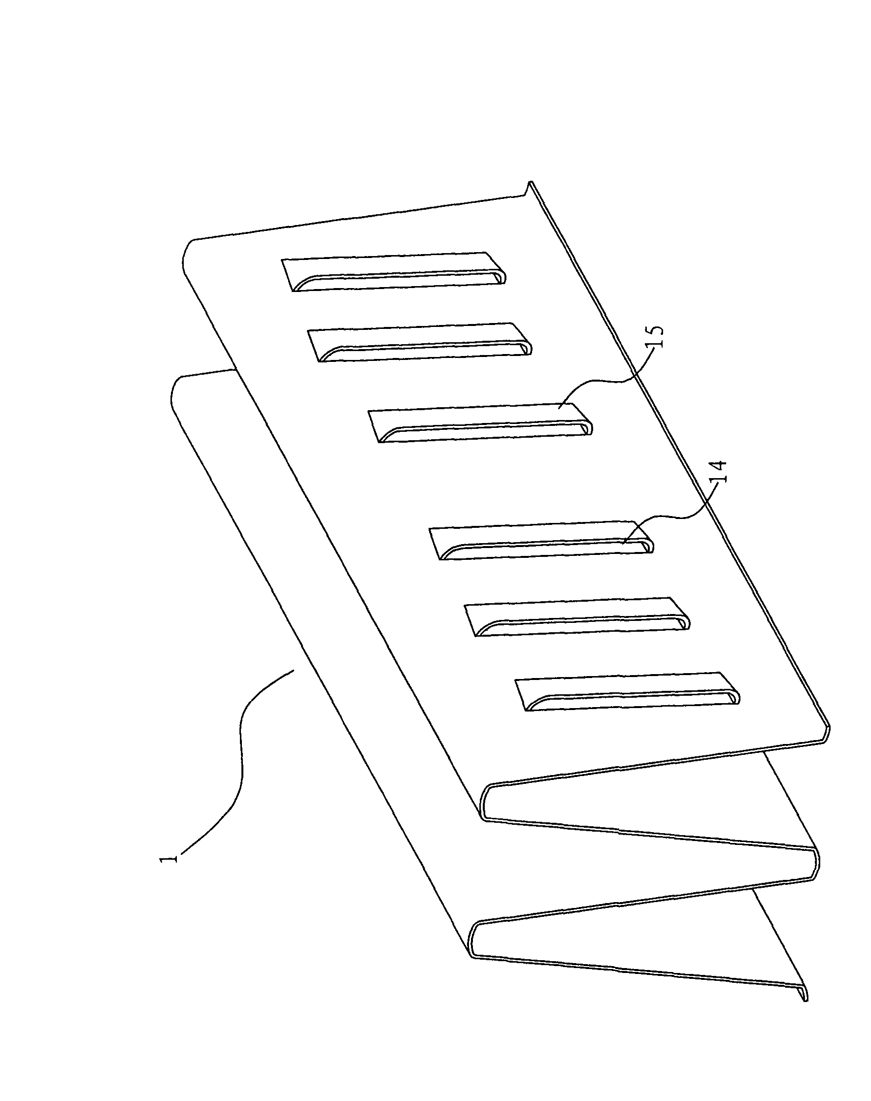
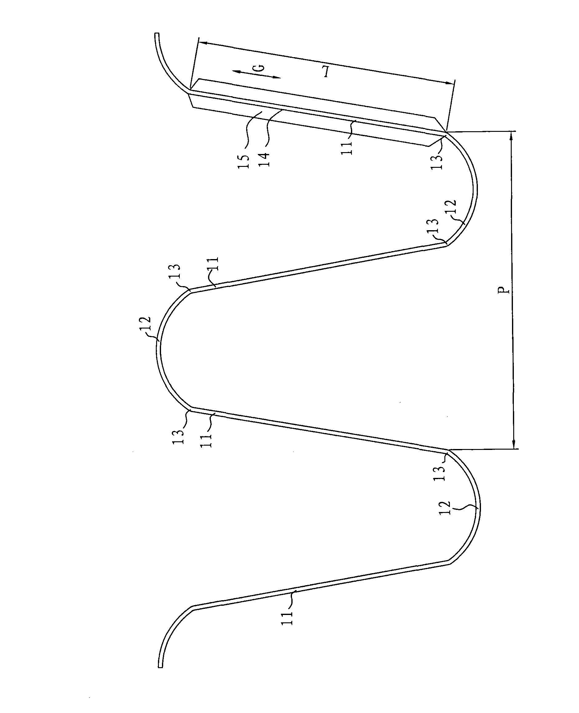
[0038] Refer below Figure 1-5 The fin 1 of the heat exchanger according to the embodiment of the present invention is described, and the heat exchanger is, for example, a micro-channel heat exchanger, but the present invention is not limited thereto.
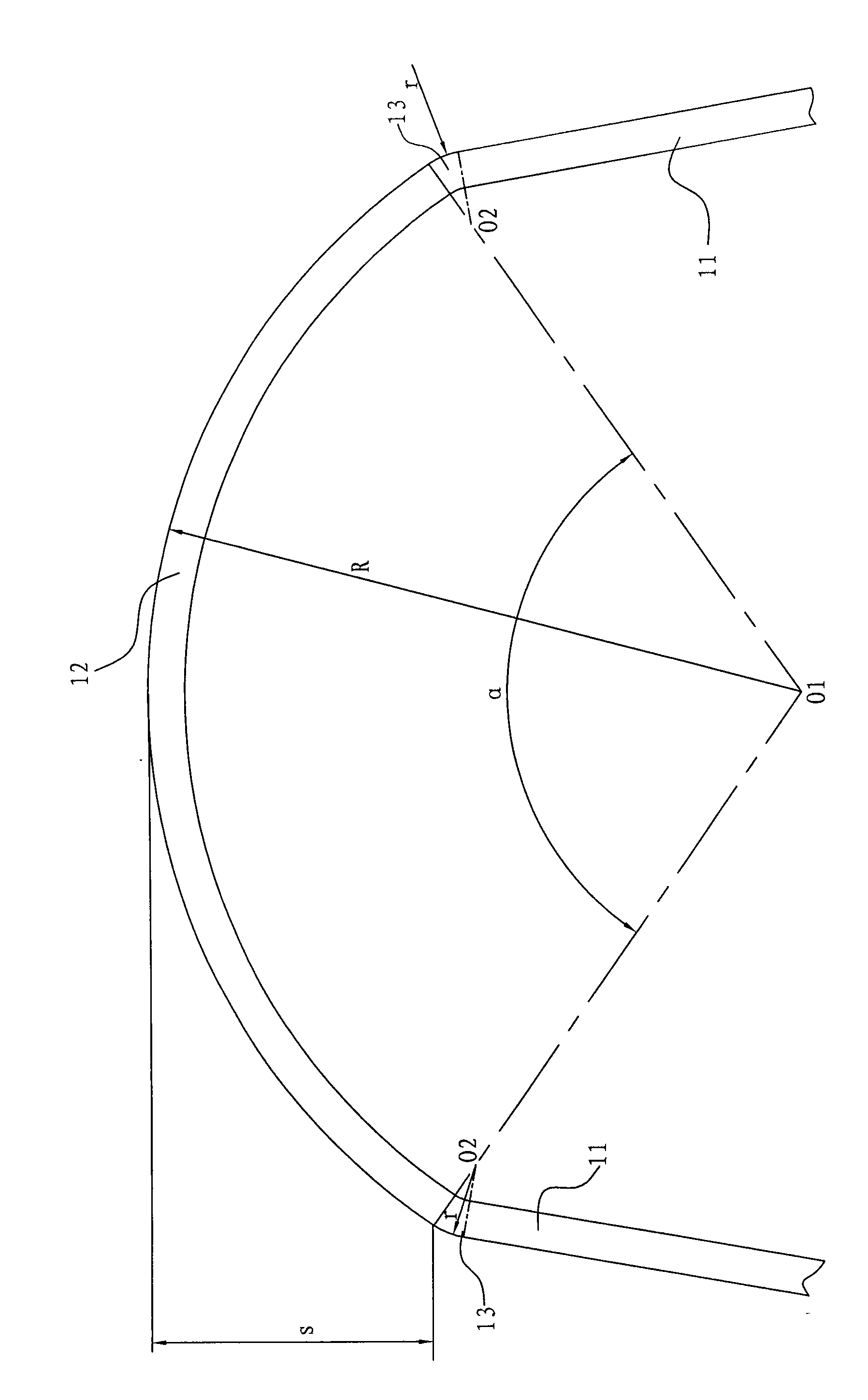
[0039] figure 1 shows a schematic perspective view of the fin 1 according to an embodiment of the present invention before being assembled and welded to the heat exchanger, figure 2 is a schematic side view of fin 1, image 3 yes figure 2 A partially enlarged schematic diagram of...
PUM
 Abstract
Description
Claims
Application Information