

Safety buckle
A buckle and safety technology, applied to buckles, fasteners, clothing, etc., can solve the problem of low safety
- Summary
- Abstract
- Description
- Claims
- Application Information
AI Technical Summary
Problems solved by technology
Method used
Image

Examples
Embodiment Construction
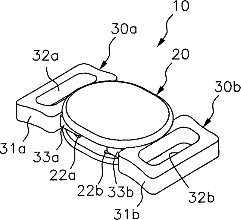
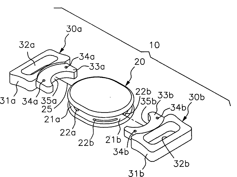
[0053] exist figure 2 , showing the appearance of a safety buckle 10, image 3 for its component decomposition state, Figure 4 for its planar shape, Figure 5Represent its internal shape, which can be used to illustrate the technical content of the present invention. The safety buckle 10 includes an intermediate member 20, which has a first groove 21a and a second groove 21b opposite to each other. The upper surface and the lower surface of the first groove 21a respectively have two left-right symmetry, and are in the same circular arc. The arc-shaped groove 22a on the top, the upper surface and the lower surface of the second groove 21b also have two left-right symmetrical grooves 22b on the same arc; that is to say, the first groove The inner surfaces of the cavity 21a and the second groove cavity 21b each have four arc-shaped grooves 22a and 22b. In fact, the two circular arc-shaped grooves 22a and 22b symmetrically arranged on the same upper and lower surfaces can al...
PUM
 Abstract
Description
Claims
Application Information