Mapping method of pilot frequency and physical resource block special for downstream and transmitting device thereof

A technology of physical resource blocks and dedicated pilots, which is applied in the field of mapping of downlink dedicated pilots and physical resource blocks and their transmitters, can solve the problems of beamforming weight feedback overhead and the inability of common pilots to obtain all channel information, etc. To achieve the effect of avoiding feedback overhead

Inactive Publication Date: 2013-01-16
ZTE CORP
View PDF0 Cites 0 Cited by
  • Summary
  • Abstract
  • Description
  • Claims
  • Application Information

AI Technical Summary

Problems solved by technology

[0004] As mentioned above, in the version of the existing LTE standard, when the base station uses beamforming with more than 4 antennas, the common pilot cannot obtain all channel information, and there is a problem of feedback overhead of beamforming weights

Method used


Image

  • Mapping method of pilot frequency and physical resource block special for downstream and transmitting device thereof
  • Mapping method of pilot frequency and physical resource block special for downstream and transmitting device thereof
  • Mapping method of pilot frequency and physical resource block special for downstream and transmitting device thereof

Examples


application example 1

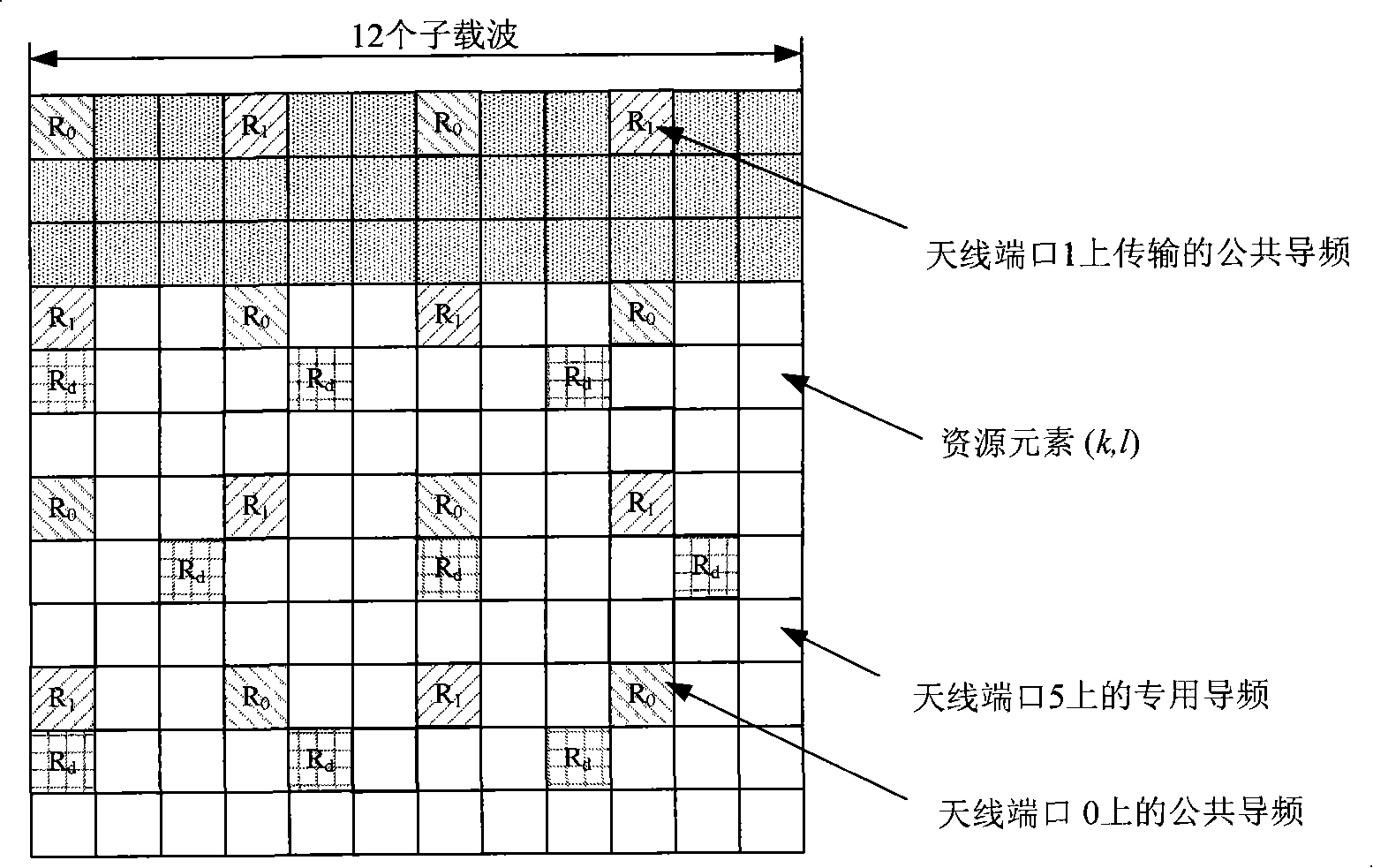
[0071] Such as Figure 3A As shown, in this example, the control information occupies the 0th to 2nd OFDM symbols, A=1, B=5, and one physical resource block contains 9 downlink dedicated pilots. The simulation proves that the overhead is small and the performance is good. The first row of downlink-specific pilots is located on the fifth OFDM symbol, the second row of downlink-specific pilots is separated by two OFDM symbols, and is located on the eighth OFDM symbol; the third row of downlink-specific pilots is separated from the second row by three OFDM symbol, located on the eleventh OFDM symbol. As for the two downlink dedicated pilots on the same OFDM symbol, they are spaced by 3 subcarriers, and the specific frequency domain positions are shown in the figure. The specific transmitting ports of the above common pilot and downlink dedicated pilot may implement the current standard, which is not limited in the present invention.

[0072] As a supplementary mapping method, ...

application example 2

[0074] Such as Figure 4 shown. In this example, the control information occupies the 0th to 2nd OFDM symbols. Since A=3 and B=5, the first downlink dedicated pilot is located on the fifth OFDM symbol, and the second downlink dedicated pilot is separated by two OFDM symbols. The symbol is located on the eighth OFDM symbol; the third row of downlink dedicated pilot is separated from the second row by three OFDM symbols, and is located on the eleventh OFDM symbol.

[0075] As can be seen from the above description, in the present invention, by presetting the frequency domain interval and the time domain interval, and determining the position of the first downlink dedicated pilot (frequency domain initial position and time domain initial position), and According to a predetermined rule, the position of the pilot symbol in the physical resource block can be determined.


PUM


Abstract

The invention relates to a mapping method of downstream special pilot frequency and physical resource block, which is used for mapping the downstream special pilot frequency and the physical resource block in a long-term evolution system. The physical resource block comprises 12 subcarriers in a frequency domain and comprises 12 orthogonal frequency division multiplexing (OFDM) symbols in a time domain; when a wave beam is formed, a transmitting end maps one of a plurality of downstream special pilot frequencies into the physical resource block and OFDM symbols with different public pivot frequencies, two or three OFDM symbols are arranged between every two adjacent OFDM symbols mapped with the downstream special pilot frequency, three downstream special pilot frequencies are mapped into the same OFDM symbol, and the interval between every two downstream special pilot frequencies is three subcarriers. The invention also provides a corresponding transmitting device. The invention can carry all channel information in the pilot frequencies of the physical resource block by smaller cost.

Description

technical field [0001] The invention relates to a method for mapping downlink dedicated pilots and physical resource blocks in a long cyclic prefix frame structure in a long term evolution system (Long term evolution, LTE for short) in the field of mobile communications. Background technique [0002] In the current version of the LTE (Long term evolution, long-term evolution system) standard 3GPP (3rdGeneration partnership project, third generation mobile communication partnership project) TR 36.211, the beamforming technology supporting single stream is stipulated. Coding also clarifies the condition that beamforming is applied to the number of antennas greater than or equal to four. However, only four common pilots are defined in the current version of the LTE standard, so only four common pilots are used in practice, and the channel information of each antenna port is extracted from the corresponding common pilot. Therefore, when the number of antennas is greater than fo...

Claims


Application Information

Patent Timeline
Patent Type & Authority Patents(China)
IPC IPC(8): H04L27/26H04J11/00
Inventor 姜静
Owner ZTE CORP
Why Eureka
Try Eureka