
Circular knitting machine with a rotatable installed dial

A circular knitting machine, needle disc technology, applied in the direction of circular knitting, knitting, weft knitting, etc. for weft knitting with individual action needles

Active Publication Date: 2009-10-28
SIPRA PATENTENTWICKLUNGS & BET GMBH
View PDF3 Cites 2 Cited by
  • Summary
  • Abstract
  • Description
  • Claims
  • Application Information

AI Technical Summary

Problems solved by technology

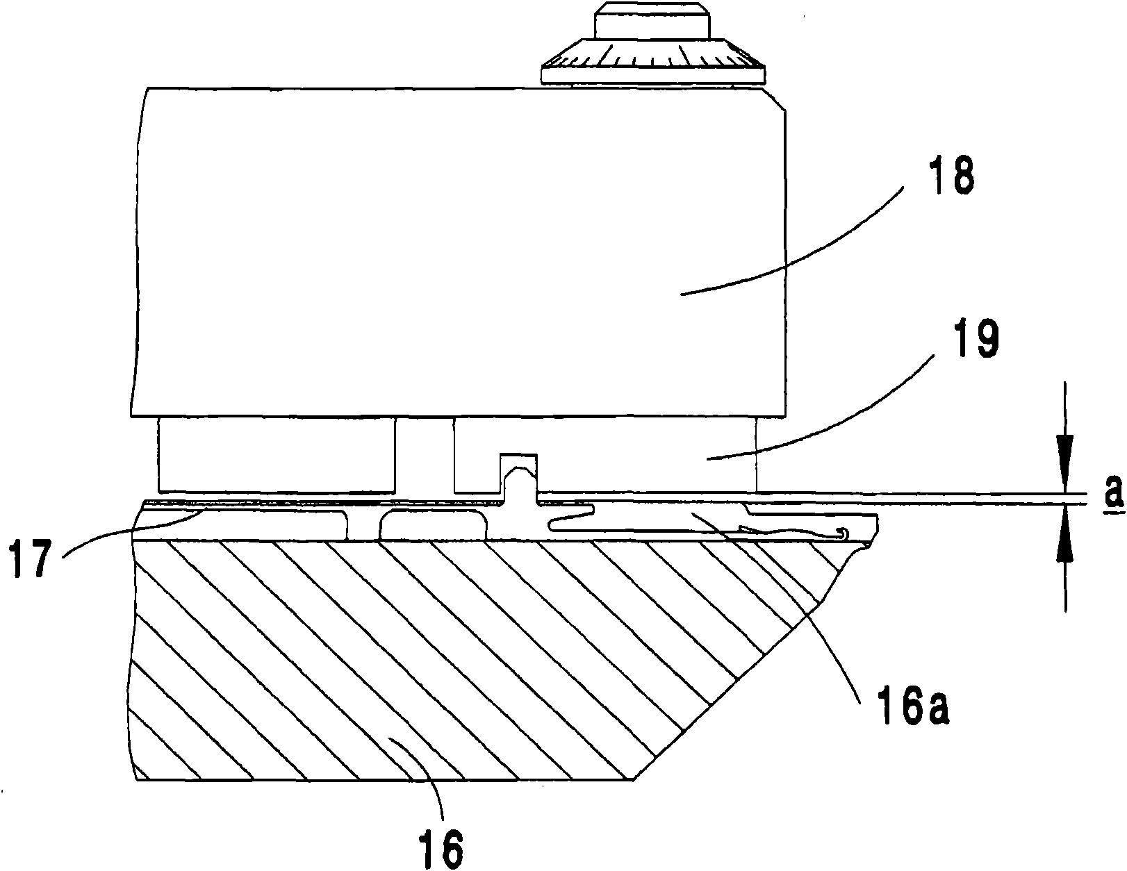
Although these fluctuations are only in the order of microns, they still mean that trouble-free electromagnetic needle selection of dial needles is no longer possible

Method used


Image

  • Circular knitting machine with a rotatable installed dial
  • Circular knitting machine with a rotatable installed dial
  • Circular knitting machine with a rotatable installed dial

Examples


Embodiment Construction

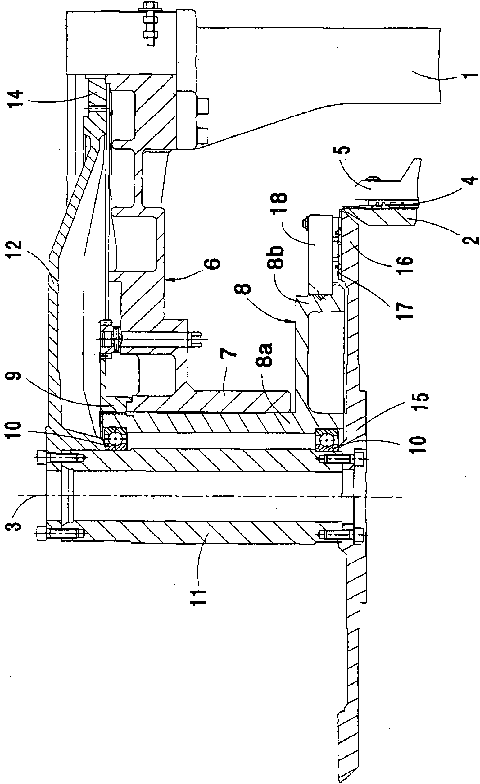
[0013] figure 1 shows a conventional circular knitting machine, with frame 1, in figure 1 Only one of its vertical columns is shown in . A fixed lower support ring (not shown) is fixed in the frame 1, in which is arranged a syringe 2 which is rotatable about a rotation axis 3 and which can be driven in rotation using a conventional drive motor. The usual knitting needles 4 are arranged axially displaceable in the cylinder 2, the knitting needles 4 being moved in the usual manner by means of cylinder cams 5 .

[0014] In the upper part of the circular knitting machine, the columns of the frame 1 are connected to the upper support ring 6 with bearing bushes 7 coaxial with the axis of rotation 3 and in which a fixed dial cam support 8 is arranged The hollow cylindrical part 8a. This hollow cylindrical part 8 a has an externally threaded part at the upper end which is screwed into an internally threaded part of an adjustment wheel 9 arranged axially immovable but rotatable in t...


PUM


Abstract

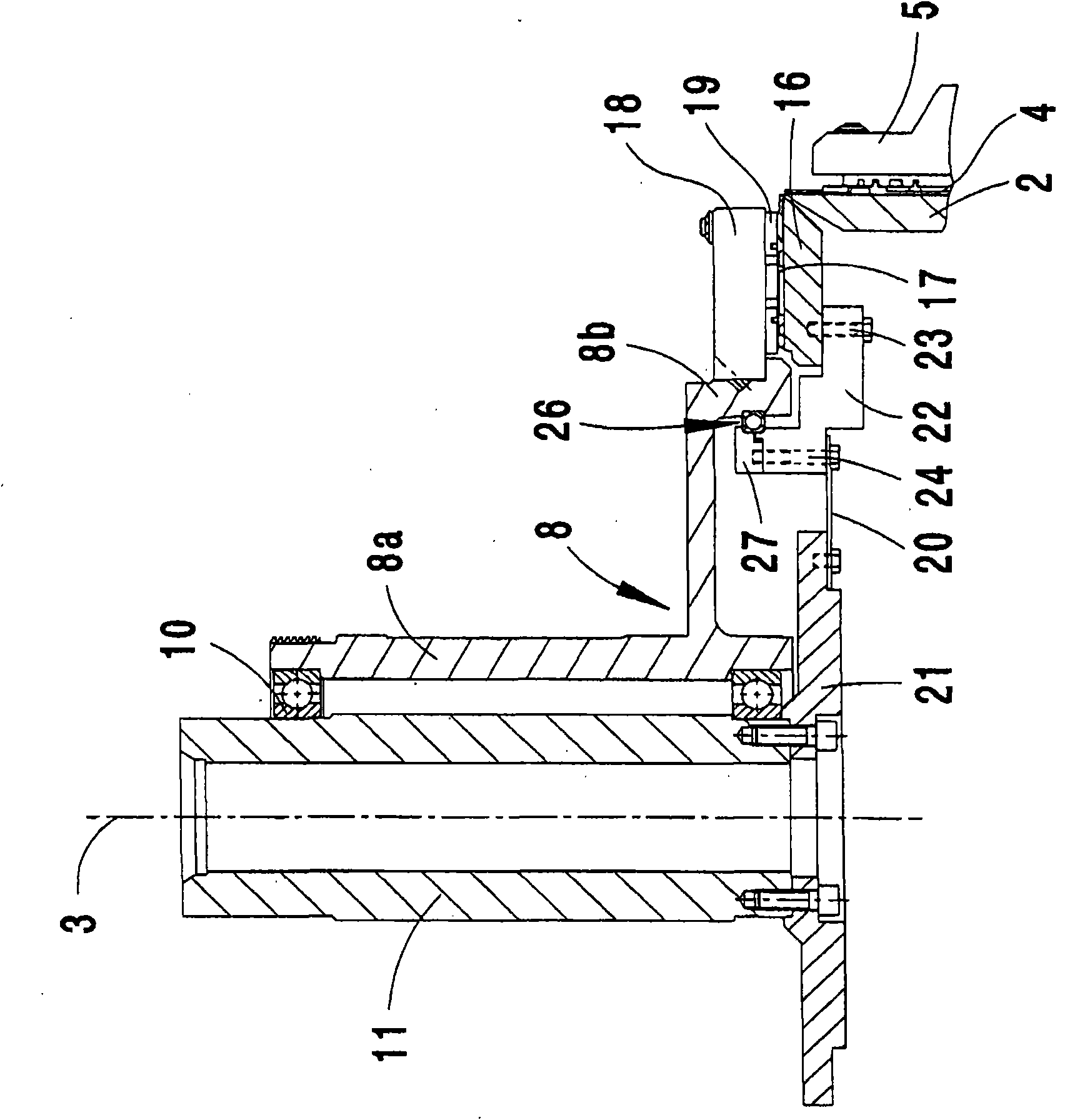
A circular knitting machine has a frame, a rotatably disposed dial, a dial cam support for a dial cam mounted in the frame and a dial cam shaft, which is disposed rotatably and coaxially in the dial cam support and is intended for driving the dial. The dial is disposed rotatably and coaxially on the dial cam support with adjustable bearing clearance and is preferably connected coaxially to the dial cam shaft by a spring plate.

Description

technical field [0001] The invention relates to a circular knitting machine of the type stated in the preamble of claim 1 . Background technique [0002] Circular knitting machines of this type are known in many variants (eg EP 0436313, B1, DE 195 11 949 A1, PCT WO 02 / 053817 A1). They are generally configured as circular rib knitting machines which, in addition to having rotatably arranged dials, also have likewise rotatably arranged needle cylinders. For the rotatable installation of the dial, the frame is provided with a fixedly arranged dial cam support, wherein a dial cam shaft is rotatably arranged in the dial cam support, the dial cam shaft is used to drive the dial and For example a rigid support ring is attached to the dial. A dial cam is fastened to the dial cam support, said dial cam having a dial cam portion and for controlling the movement of dial needles arranged radially movable in the dial. In addition, the dial cam can have patterning attachments for dial ...

Claims


Application Information

Patent Timeline
Patent Type & Authority Applications(China)
IPC IPC(8): D04B9/00D04B15/18D04B15/94
CPCD04B9/06D04B15/18
Inventor D·特伦克勒
Owner SIPRA PATENTENTWICKLUNGS & BET GMBH
Learn More