Dynamic pressure bearing and fan structure using dynamic pressure bearing and assembly method of dynamic pressure bearing

A technology of dynamic pressure bearings and bearings, applied in the field of dynamic pressure bearings, which can solve problems such as the deflection of the rotation axis of the rotating shaft 6 fan blades, the easy wear of the rotating shaft, and the reduction of the bearing area of ​​the oil film, so as to reduce the vibration and noise of the fan operation and improve the operation The effect of stability and large oil film bearing area

Active Publication Date: 2016-02-03
TUNG PEI IND
View PDF7 Cites 0 Cited by
  • Summary
  • Abstract
  • Description
  • Claims
  • Application Information

AI Technical Summary

Problems solved by technology

[0007] 1. Since the dynamic pressure bearing 8 must be sleeved inside the shaft sleeve 7, and it is necessary to further provide a pressure ring 8a for pressing the dynamic pressure bearing in the shaft sleeve, it will increase the number of parts and increase the cost
[0008] 2. The dynamic pressure bearing 8 must be set inside the shaft sleeve 7, so that the diameter of the dynamic pressure bearing 8 must be reduced, and the diameter of the rotating shaft hole and the rotating shaft 6 of the dynamic pressure bearing must also be reduced. The diameter of the shaft hole and the shaft 6 of the bearing is limited, so that the bearing area of ​​the oil film between the shaft 6 and the shaft hole is reduced, which affects its operation stability
[0009] 3. The dynamic pressure bearing 8 fits inside the shaft sleeve 7 first and then is fixed on the bottom plate 1a via the shaft sleeve 7. Therefore, double fit tolerances will be generated so that the central axis of the shaft hole of the dynamic pressure bearing 8 is easily skewed, so that the shaft 6 And the rotation axis of the fan blade 3 is deflected, resulting in vibration and noise during operation
However, if the pressure ring 8a used to press the dynamic pressure bearing 8 is loose or not securely fastened, the relative rotation between the dynamic pressure bearing 8 and the shaft sleeve 7 will occur.
[0011] 5. The commonly used dynamic pressure bearing 8 is fitted inside the shaft sleeve 7. However, due to the miniaturization of the heat dissipation fan, the size of the dynamic pressure bearing 8 is also quite small. As long as it is slightly pressed by the shaft sleeve 7, it may make the The size or roundness of the rotating shaft hole of the dynamic pressure bearing 8 is affected, which will cause errors in the size of the gap between the rotating shaft hole of the dynamic pressure bearing 8 and the rotating shaft 6 or uneven gaps, which will cause the oil film to fail to establish. So that the shaft is prone to wear and tear
[0012] 6. In addition, most of the commonly used methods of forming the oil guide groove in the dynamic pressure bearing structure are to form the oil guide groove on the inner wall of the shaft hole of the dynamic pressure bearing by etching or molding. However, the commonly used In the manufacturing method, the size and depth precision of the oil guide groove cannot be precisely controlled, so the dynamic pressure bearing cannot effectively establish an oil film

Method used


Image

  • Dynamic pressure bearing and fan structure using dynamic pressure bearing and assembly method of dynamic pressure bearing
  • Dynamic pressure bearing and fan structure using dynamic pressure bearing and assembly method of dynamic pressure bearing
  • Dynamic pressure bearing and fan structure using dynamic pressure bearing and assembly method of dynamic pressure bearing

Examples


no. 1 example 〕

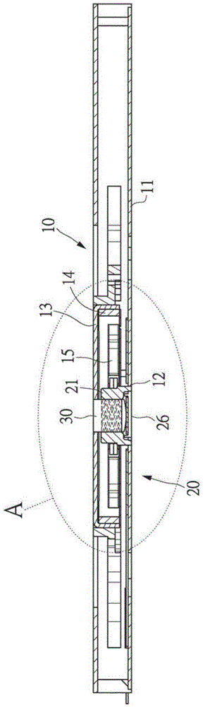
[0081] The present invention provides a dynamic pressure bearing and a fan structure using the dynamic pressure bearing, such as figure 1 Shown is a combined sectional view of a fan structure 10 using the dynamic pressure bearing of the present invention, wherein the fan structure 10 includes a bottom plate 11 , a fan blade 13 , a rotor 14 , a stator 15 and a dynamic pressure bearing assembly 20 .

[0082] The dynamic pressure bearing assembly 20 is installed on a fixed seat 12 on the bottom plate 11 , and the fan blade 13 is installed on the upper end of a rotating shaft 30 of the dynamic pressure bearing assembly 20 . The stator 15 is fixedly installed on the outer side of the dynamic pressure bearing assembly 20 , and the rotor 14 is installed on the inner side of the fan blade 13 and surrounds the outer side of the stator 15 . The rotor 14 and the stator 15 can generate mutually repulsive magnetic fields to drive the fan blades 13 to rotate.

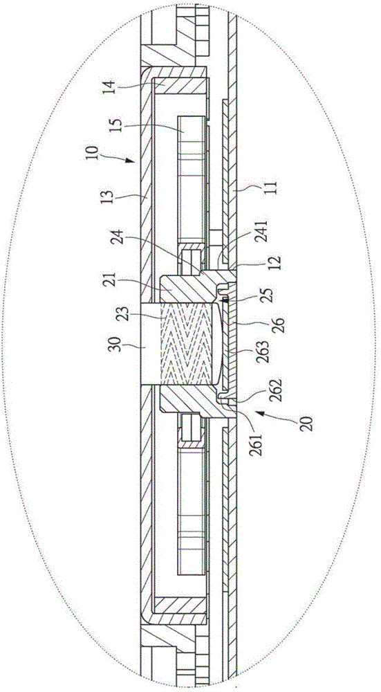
[0083] like figure 2 As s...

no. 2 example

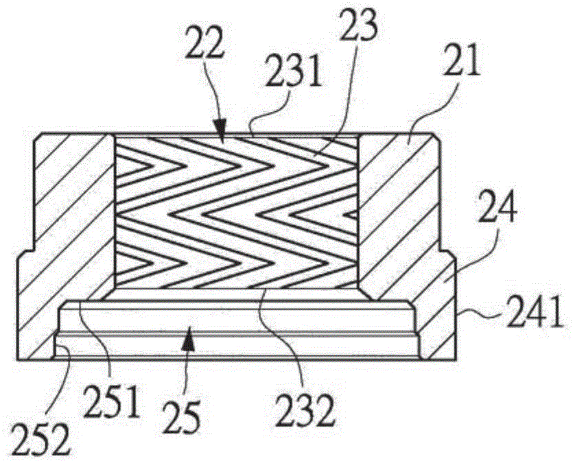
[0106] like Figure 8 Shown is the second embodiment of the present invention, and the second embodiment is an embodiment in which the technology of the present invention is applied to a thick heat dissipation fan module. The fan structure 10 and the dynamic pressure bearing assembly 20 in this embodiment have higher heights, and the heights of the bearing body 21 and the rotating shaft 30 are also higher than those of the bearing body 21 and the rotating shaft 30 in the first embodiment. In the second embodiment, the shaft hole 22 of the bearing body 21 has more than one row of oil guide grooves 23 inside.

[0107] like Figure 8 In the shown embodiment, the inner wall surface of the shaft hole 22 of the bearing body 21 is arranged along the axial direction of the shaft hole 22 with two rows of oil guide grooves 23, and an isolation groove is arranged between the two rows of oil guide grooves 23 233 isolates the two rows of oil guide grooves 23. The function of the isolati...


PUM


Abstract

The invention discloses a dynamic pressure bearing and a fan structure using the dynamic pressure bearing and an assembly method of the dynamic pressure bearing. The dynamic pressure bearing comprises a bearing body, a bearing fixing part, an oil storage chamber, a bottom cover and a rotation shaft. The bearing body is provided with a rotation shaft hole. The inner side wall of the rotation shaft hole is provided with a plurality of herringbone oil guide grooves. The rotation shaft can be rotationally attached to the rotation shaft hole in a sleeved mode. The bearing fixing part is connected to the bottom end of the bearing body in an integral-forming mode. The bearing fixing part is provided with a connection face and connected with a fixing seat through the connection face, thereby being fixed to the fixing seat. Meanwhile, the oil storage chamber is arranged at the bottom end of the bearing fixing part, and the bottom cover is arranged at an opening of the oil storage chamber to seal the oil storage chamber.

Description

technical field [0001] The invention relates to a dynamic pressure bearing suitable for use in a cooling fan system, a fan structure using the dynamic pressure bearing and an assembly method thereof. Background technique [0002] Press, the cooling fan is one of the main components in the cooling module. In recent years, in order to meet the trend of miniaturization and thinning of information products such as notebook computers and tablet computers, and the continuous improvement of processor operating power, the heat dissipation module must also be miniaturized and thinner while taking heat dissipation into consideration. direction of efficiency improvement. Therefore, the fan used in the heat dissipation module must also be reduced in size and thickness, and at the same time, the fan speed must be increased. In order to meet the needs of miniaturization, thinning and high speed of fans, quite a lot of cooling fans have changed to the design of dynamic pressure bearings ...

Claims


Application Information

Patent Timeline
Patent Type & Authority Applications(China)
IPC IPC(8): F04D29/056F04D29/66F04D29/063F04D25/08F04D29/64
Inventor 陈友约涂栋文陈维瀚
Owner TUNG PEI IND
Why Eureka
Try Eureka