
Mud-sucking device provided with dredging mechanism

A mud suction pipe and mud collecting tank technology, which is applied in the direction of mechanically driven excavators/dredgers, can solve the problems of inconvenient mud suction pipes, sludge blockage, low work efficiency, etc., and achieve the effect of dredging and easy to see.

Active Publication Date: 2009-11-18
WUXI GENERAL MACHINERY FACTORY
View PDF0 Cites 2 Cited by
  • Summary
  • Abstract
  • Description
  • Claims
  • Application Information

AI Technical Summary

Problems solved by technology

During the working process, the mud suction pipe 4 is often blocked by mud, which will affect the normal mud discharge effect after the blockage
In the prior art, once the mud suction pipe is blocked, the mud can only be discharged manually, which is both troublesome and low in work efficiency
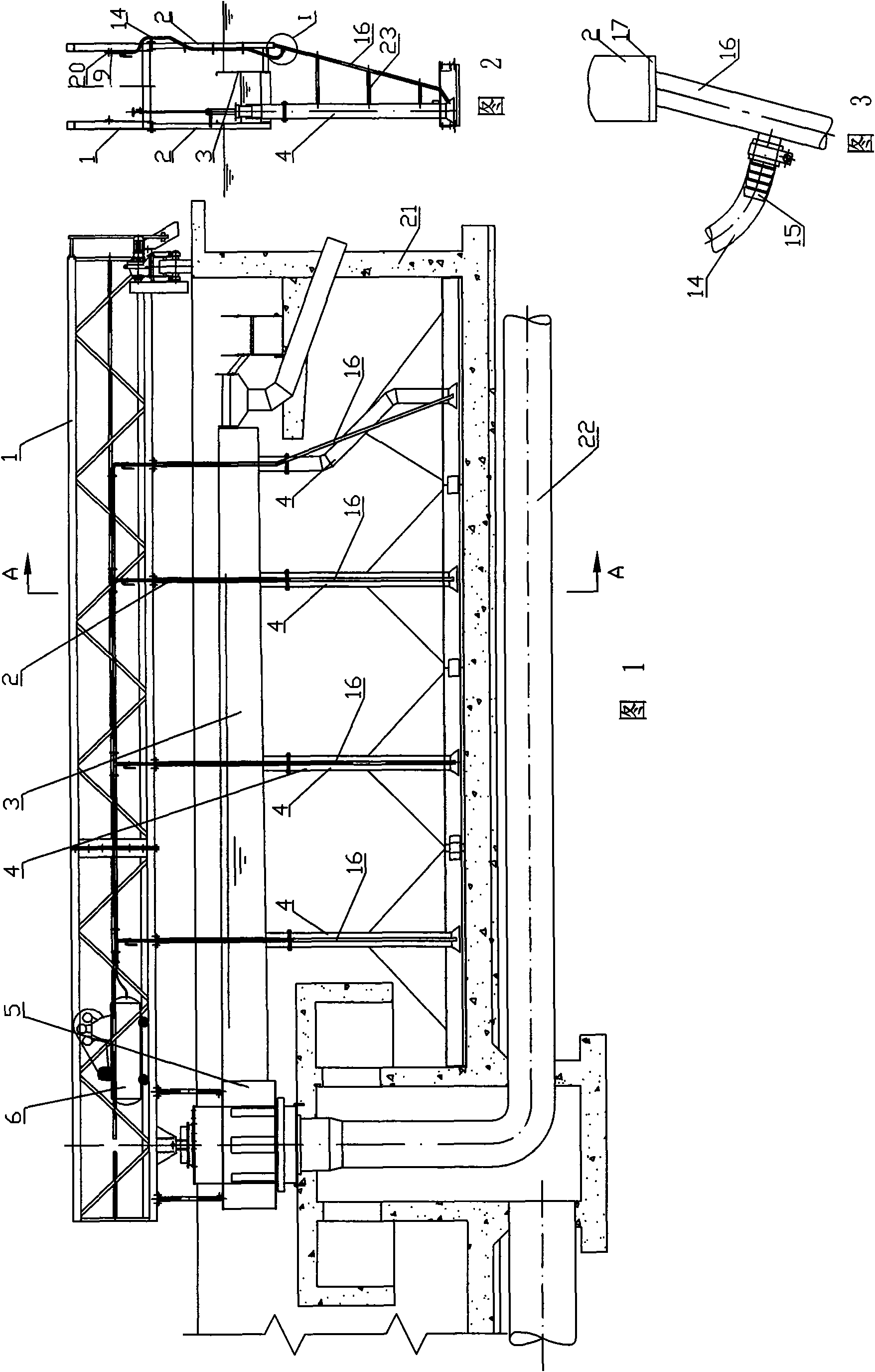
[0003] The dredging device for the dredging pipe can solve the problem that the dredging pipe 4 is blocked by mud balls or other debris and affects the normal mud discharge effect, and it is very inconvenient to dredge the dredging pipe manually

Method used


Image

  • Mud-sucking device provided with dredging mechanism
  • Mud-sucking device provided with dredging mechanism
  • Mud-sucking device provided with dredging mechanism

Examples


Embodiment Construction

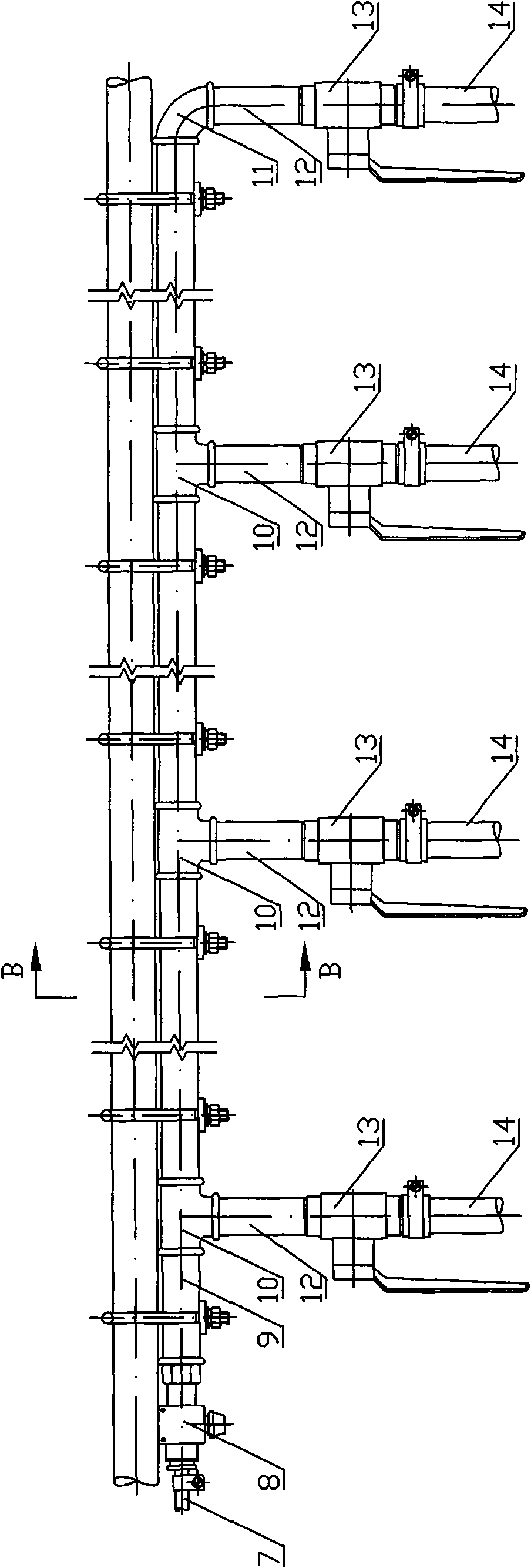
[0015] As shown in the figure: the mud suction device with a dredging mechanism includes the working bridge 1 and the mud collecting tank 3 located below the working bridge 1. The inner end of the mud collecting tank 3 arranged in the horizontal direction is the central mud tank 5. Several vertically arranged dredging pipes 4 are arranged below the groove 3, and a total dredging pipe 22 is arranged below the center mud tank 5; 4 corresponds to the branch pipes 12 one by one, and the outlet end of each branch pipe 12 is connected to the bottom of the corresponding dredge pipe 4 by means of a respective air branch rubber pipe 14 .

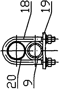
[0016] The outlet end of the air branch rubber pipe 14 can be connected with the cable-stayed pipe 16 first, and the outlet end of the cable-stayed pipe 16 is then connected with the bottom of the suction pipe 4 . The main air hose 7 should be installed at the inlet end of the main pipe 9, and the inlet end of the air hose 7 is connected to the air c...


PUM


Abstract

The invention relates to a mud-sucking device provided with a dredging mechanism. According to the technical proposal provided by the invention, the mud-sucking device provided with the dredging mechanism comprises a working bridge and a mud-collecting trough positioned below the working bridge, wherein the inner end of the mud-collecting trough which is arranged transversely is provided with a central mud tank, a plurality of mud-sucking pipes are vertically arranged below the mud-collecting trough, and a header mud pipe is arranged below the central mud tank. The mud-sucking device is characterized in that the working bridge is provided with a main pipe, the main pipe is provided with branch pipes which are in one-to-one correspondence with the mud-sucking pipes, and the outlet end of each branch pipe is connected with the bottom of a corresponding mud-sucking pipe by using respective air support hose. The mud-sucking device has the advantages of needing no operation in water, being simple and practical, dredging a single mud-sucking pipe or a plurality of the mud-sucking pipes at the same time, and being intuitive and easy to see whether the mud-sucking pipes are dredged.

Description

technical field [0001] The invention relates to a peripheral drive mud suction machine, in particular to a mud suction device with a dredging mechanism. Background technique [0002] The peripheral transmission dredger is mainly used to remove the sludge in the pool. In the peripheral transmission dredger, the variable cross-section mud collection tank 3 is hung on the lower part of the working bridge 1 through the boom 2, and rotates with the rotation of the working bridge 1. . The mud collecting tank 3 is U-shaped with an upper opening, and the end close to the pool wall 21 is sealed by a sealing plate, and the end close to the center of the pool is connected to the central mud tank 5, and the mud collecting tank 3 is equipped with suction mud arranged in the diameter direction of the sedimentation tank. Tube 4 is in communication with each other. Because the liquid level in the mud collecting tank 3 is lower than the liquid level outside the mud collecting tank 3, the m...

Claims


Application Information

Patent Timeline
Patent Type & Authority Applications(China)
IPC IPC(8): E02F3/88E02F3/90
Inventor 顾红兵张兴斌李承钟
Owner WUXI GENERAL MACHINERY FACTORY
Learn More