
Electronic equipment

A technology for electronic equipment and buttons, which is applied in electrical digital data processing, instruments, digital data processing components, etc.

Inactive Publication Date: 2011-09-28
SONY CORP +1
View PDF1 Cites 0 Cited by
  • Summary
  • Abstract
  • Description
  • Claims
  • Application Information

AI Technical Summary

Problems solved by technology

[0005] However, if such a light-shielding part is provided, the user who operates the electronic device from the front will be blocked by the light-shielding part and cannot confirm the light emission of the power switch.

Method used


Image

  • Electronic equipment
  • Electronic equipment
  • Electronic equipment

Examples


Embodiment Construction

[0056] Hereinafter, embodiments of the present invention will be described based on the drawings.

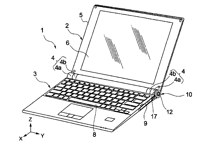
[0057] In this embodiment, a notebook computer will be described as an example of an electronic device.

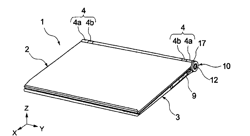
[0058] figure 1 It is a perspective view of an unfolded state of an electronic device according to an embodiment of the present invention, figure 2 yes figure 1 A perspective view of the closed state of the electronic device shown.

[0059] Electronic device 1 includes display unit 2 , main body unit 3 , and hinge 4 connecting display unit 2 and main body unit 3 .

[0060] The display part 2 can be opened and closed relative to the main body part 3 through the hinge 4 . The display unit 2 has a display side housing 5 , a display surface 6 , and a display processing unit (not shown) provided in the display side housing 5 that performs display processing.

[0061] The display side housing 5 is a housing that accommodates the display unit 2 of a display processing unit (...


PUM


Abstract

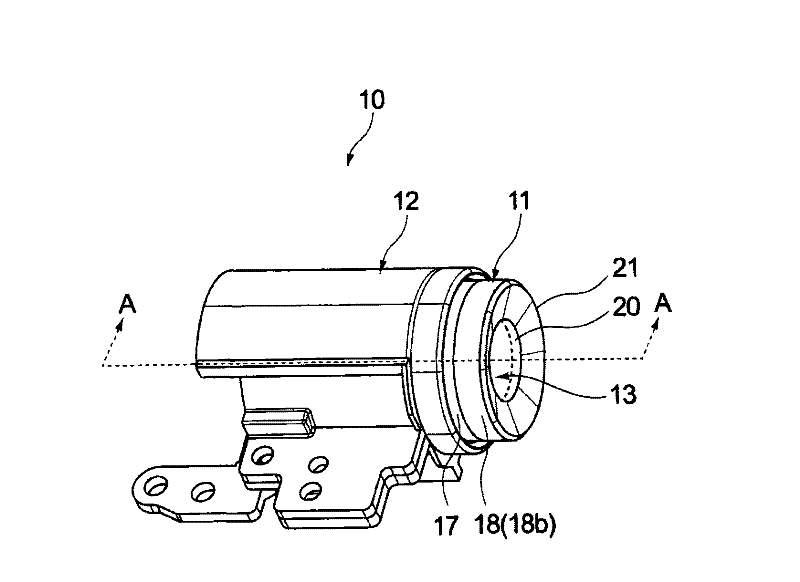
Provided is electronic equipment, wherein a user who operates the electronic equipment is capable of recognizing lighting states without the damage of design. A power supply switch unit (10) is provided with a shading part (18) locating in a corresponding region of the cirumferential surface of a button (13) and a annular transparent part (17) locating in a corresponding region of a part of the cirumferential surface of a holding member (14). The rays emitted from a lighting element (36) are projected on a second surface (27) of the holding member (14) and is permeated the button (13) after the scatter of a scattering film (26), at the same time, the rays are reflected by the scattering film (26) of a first surface (24) and is expanded radiatably to pass through the annular transparent part (17). As a result, the rays from the lighting element (36) are emitted radiating from the annular transparent part (17). Thus, it is capable of recognizing the lighting states of the power supply switch unit (10) of the electronic equipment (1) through a posture of observing a display surface (6) under a condition of keeping a depositing and ensuring the design.

Description

technical field [0001] The invention relates to electronic equipment such as notebook computers. Background technique [0002] Electronic devices such as notebook computers are required to arrange buttons such as power switches without hindering the reduction in size and thickness while improving the design. According to Patent Document 1, a power switch is provided at one end of a hinge that rotatably connects a housing provided with a keyboard and the like to a housing provided with a display unit. For example, when the power is turned on, the power switch makes the switch emit light through the light emitting element. Thereby, it is possible to visually and very easily know the state, for example, that the power is turned on. [0003] [Patent Document 1] Japanese Unexamined Patent Publication No. 2005-128805 (paragraph [0135], figure 2 , Figure 25, etc.) [0004] In the technique described in Patent Document 1, since the power switch is exposed at one end of the hinge...

Claims


Application Information

Patent Timeline
Patent Type & Authority Patents(China)
IPC IPC(8): G06F1/16
Inventor 中村裕二周文臣
Owner SONY CORP
Learn More