Indoor machine for air conditioner
A technology for an air conditioner and an indoor unit, which is applied in the field of indoor units and can solve problems such as damage to the design of the indoor unit.
- Summary
- Abstract
- Description
- Claims
- Application Information
AI Technical Summary
Problems solved by technology
Method used
Image
Examples
no. 1 Embodiment approach
[0046] (1) Composition
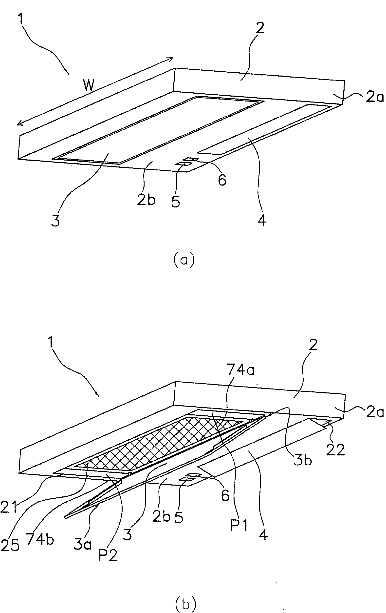
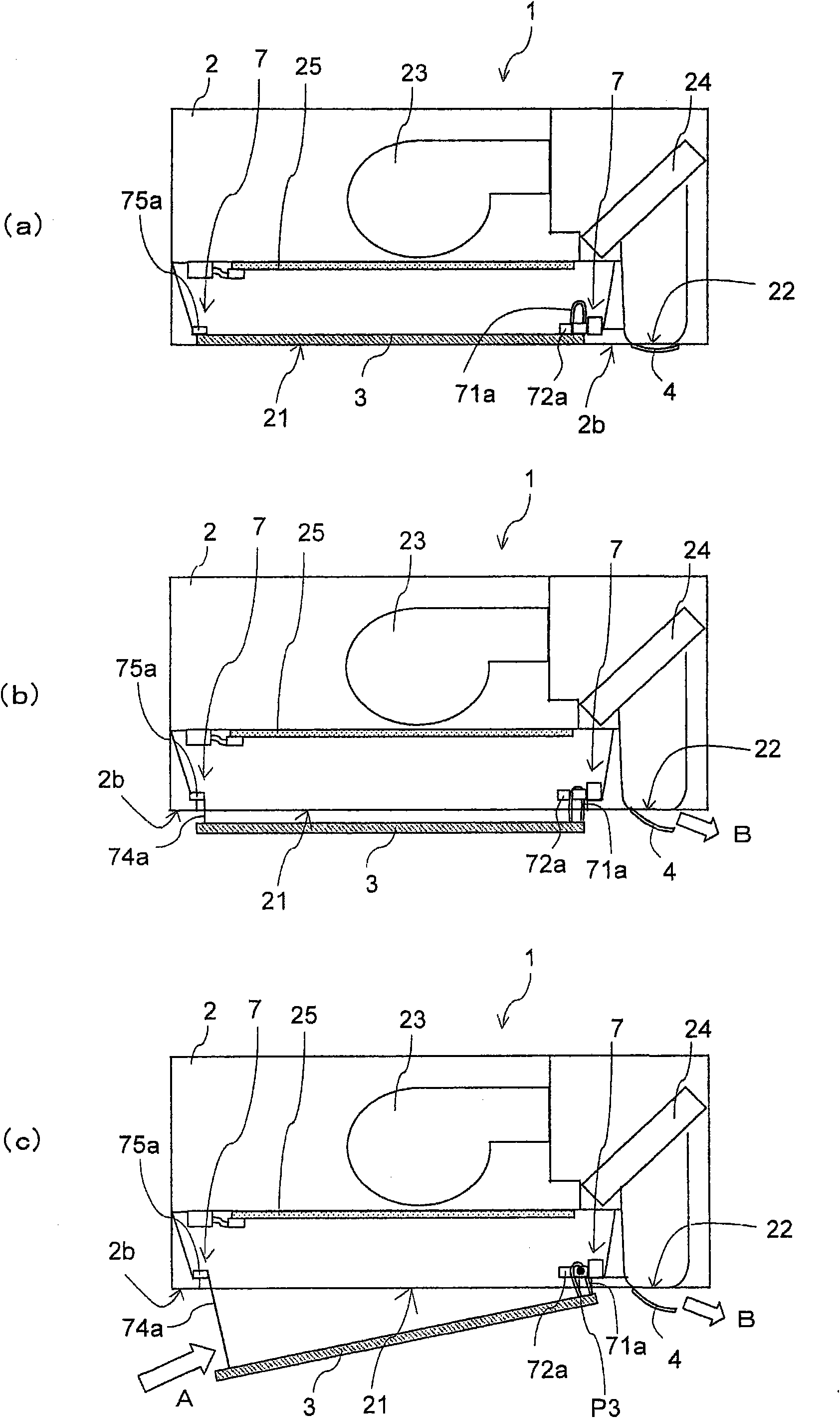
[0047] figure 1 (a) and (b) are perspective views of the indoor unit 1 of the air conditioner according to the present embodiment when the operation is stopped and when the operation is in operation, respectively. figure 2 (a) to (c) are viewed from the first side surface 2a side of the indoor unit 1 figure 1 A schematic diagram of the internal structure of the indoor unit 1. The indoor unit 1 is a so-called ceiling-mounted indoor unit installed on a ceiling indoors, and can perform heating operation, cooling operation, and the like.
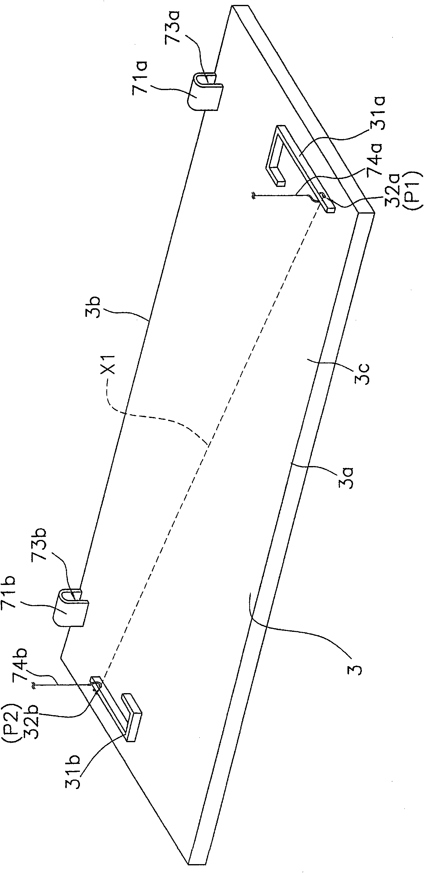
[0048] Such as figure 1 , figure 2 with Image 6 As shown, the indoor unit 1 has a main body 2 , a flat panel 3 (equivalent to a panel), a horizontal baffle 4 , a receiving part 5 , an operating state display part 6 , a panel driving part 7 and a control part 9 .
[0049] In addition, in the following, expressions such as "upper", "lower", "right", and "left" are used as appropriate, such as "below" of the main b...
no. 2 Embodiment approach
[0099] Next, use Figure 7 with Figure 8 The indoor unit 101 of the air conditioner according to the second embodiment of the present invention will be described. Figure 7 (a) to (c) are schematic diagrams showing the internal structure of the indoor unit 101 according to the second embodiment, Figure 8 It is a block diagram schematically showing each device constituting the indoor unit 101 .
[0100] (1) Composition
[0101] Similar to the first embodiment, the indoor unit 101 is an indoor unit of a ceiling-mounted air conditioner. The indoor unit 101 mainly includes: a main body 102 , a flat panel 103 , a horizontal baffle 104 , a receiving unit 105 , an operating state display unit 106 , a panel driving unit 107 and a control unit 109 . One air inlet 121 and one air outlet 122 are formed on the lower surface of the main body 102 , that is, the decorative panel 102 b , and the main body 102 houses a blower fan 123 , an indoor heat exchanger 124 , and a filter 125 . I...
no. 3 Embodiment approach
[0133] Next, use Figure 10 ~ Figure 13 The indoor unit 201 of the air conditioner according to the third embodiment of the present invention will be described. Figure 10 It is a perspective view of the indoor unit 201 in operation. Figure 11 (a) to (c) are viewed from the first side surface 202a side of the indoor unit 201 Figure 10 A schematic diagram of the internal structure of the indoor unit 201. Figure 12 is an enlarged view of the flat panel 203, Figure 13 It is a block diagram schematically showing each device constituting the indoor unit 201 .
[0134] (1) Composition
[0135]Similar to the first and second embodiments, the indoor unit 201 is an indoor unit of a ceiling-mounted air conditioner, and mainly includes a main body 202, a flat panel 203, a horizontal baffle 204, a receiving part 205, an operating state display part 206, and a panel drive. part 207 and the control part 209. One suction port 221 and one blowing port 222 are formed on the lower sur...
PUM
 Abstract
Description
Claims
Application Information
 - R&D
- Intellectual Property
- Life Sciences
- Materials
- Tech Scout
- Unparalleled Data Quality
- Higher Quality Content
- 60% Fewer Hallucinations
Browse by: Latest US Patents, China's latest patents, Technical Efficacy Thesaurus, Application Domain, Technology Topic, Popular Technical Reports.
© 2025 PatSnap. All rights reserved.Legal|Privacy policy|Modern Slavery Act Transparency Statement|Sitemap|About US| Contact US: help@patsnap.com


