Audio processing device and audio output device
A processing device and audio technology, applied in signal processing, frequency/direction characteristic device, magnetostrictive sensor, etc., can solve the problem of no audio terminal with ultrasonic signal, and achieve the effect of not damaging the design
- Summary
- Abstract
- Description
- Claims
- Application Information
AI Technical Summary
Problems solved by technology
Method used
Image
Examples
Embodiment approach 1
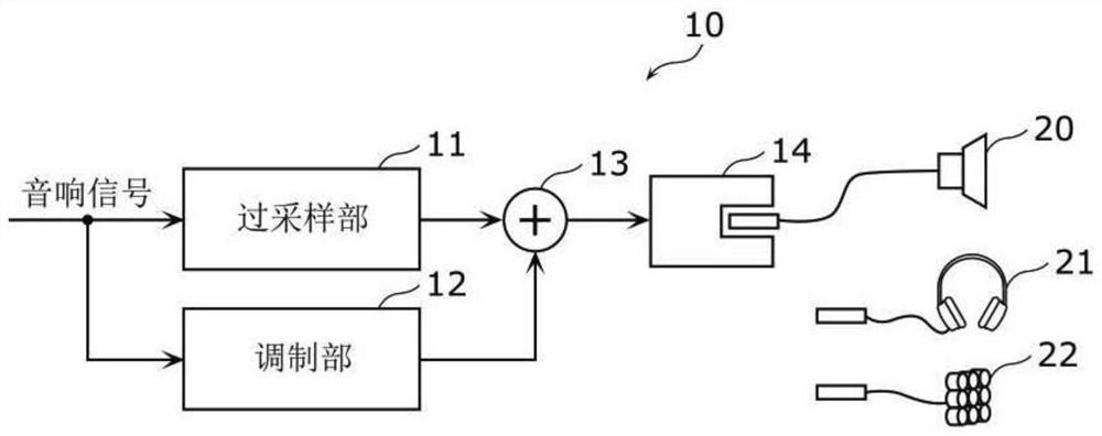
[0031] figure 1 It is a block diagram showing a configuration example of the audio processing device 10 according to the first embodiment.
[0032] The sound processing device 10 is a signal processing device that processes sound signals to output sound signals in the audible frequency range and ultrasonic signals including the sound signals, and includes an oversampling unit 11 , a modulation unit 12 , an adder 13 , and an sound output terminal 14 . In addition, in this figure, as types of speakers connected to the audio output terminal 14 , a speaker 20 for an audible frequency range, a headphone 21 , and an ultrasonic speaker 22 are shown. In addition, an "acoustic signal" is a signal broadly including all sounds, such as a musical instrument, not only a voice.
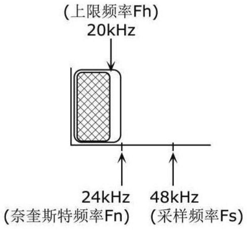
[0033] The input audio signal is a digital signal having a sampling frequency of Fs including frequency components below Fh when a preset frequency is Fh (hereinafter, Fh is also referred to as "upper limit freque...
Deformed example 1
[0059] Next, an acoustic processing device according to Modification 1 of Embodiment 1 will be described.
[0060] Figure 9 It is a block diagram showing a configuration example of an acoustic processing device 10 a according to Modification 1 of Embodiment 1. FIG. This acoustic processing device 10a differs from the acoustic processing device 10 according to Embodiment 1 in that the modulation unit 12 is replaced with a new modulation unit 12a.
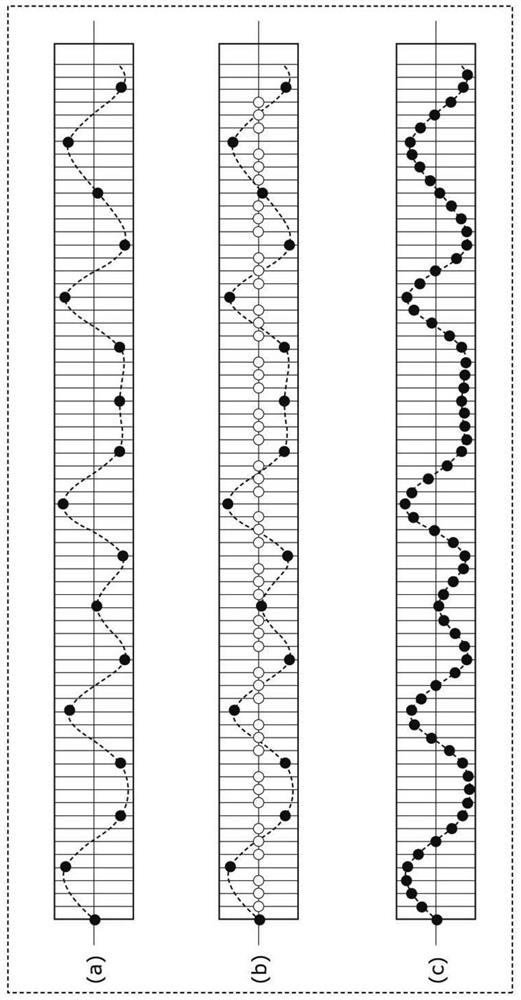
[0061] The modulator 12a uses not the sound signal input to the sound processing device 10a but the output signal from the oversampling part 11, and modulates the ultrasonic signal as a carrier wave. In Embodiment 1, in order to generate Figure 5 (a) shows a signal whose sampling frequency Fs is 192 kHz, and quadruple oversampling is performed on the sound signal input to the sound processing device 10 a. In this modified example, the modulation unit 12 a uses the output signal from the oversampling unit 11 as an input signal, t...
Deformed example 2
[0064] Next, an acoustic processing device according to Modification 2 of Embodiment 1 will be described.
[0065] Figure 10It is a block diagram showing a configuration example of an acoustic processing device 10b according to Modification 2 of Embodiment 1. FIG. This sound processing device 10b is different from the sound processing device 10 according to Embodiment 1 in that the sound signals input to the oversampling unit 11 and the modulating unit 12 are divided into different sound signals (respectively, the first sound signal and a second audio signal).
[0066] In other words, the oversampling unit 11 oversamples the first sound signal to a signal having a sampling frequency equal to or greater than 2×Fs. The modulation unit 12 modulates the second sound signal and an ultrasonic signal with a frequency Fc equal to or greater than 2×Fh as a carrier.
[0067] Here, the first sound signal is, for example, the main sound signal (main sound) of a TV broadcast, while the...
PUM
 Abstract
Description
Claims
Application Information
 - R&D
- Intellectual Property
- Life Sciences
- Materials
- Tech Scout
- Unparalleled Data Quality
- Higher Quality Content
- 60% Fewer Hallucinations
Browse by: Latest US Patents, China's latest patents, Technical Efficacy Thesaurus, Application Domain, Technology Topic, Popular Technical Reports.
© 2025 PatSnap. All rights reserved.Legal|Privacy policy|Modern Slavery Act Transparency Statement|Sitemap|About US| Contact US: help@patsnap.com


