Screw tape locking device and nail tape transmission device therein

A technology of locking devices and screw straps, which is applied to screwdrivers, wrenches, manufacturing tools, etc., can solve the problems of inaccurate screw strap displacement, inaccurate screw locking positions, and high cost, and achieve the effect of preventing the screw strap from retreating

Inactive Publication Date: 2009-12-30
陈河田
View PDF0 Cites 2 Cited by
  • Summary
  • Abstract
  • Description
  • Claims
  • Application Information

AI Technical Summary

Problems solved by technology

[0004] The common disadvantage of the above two patents is that when the gear or gear is used to drive the nail belt, there will be a transmission gap between the gear or gear and the transmission teeth of the nail belt, and when the gear or gear drives the nail belt several times, the transmission gap That is, it will be enlarged automatically, resulting in inaccurate displacement of the nail belt
Since the positioning method is to use the positioning holes in the dial, the inertia generated when the nail belt advances cannot be completely eliminated, resulting in inaccurate locking positions of the screws installed on the nail belt, and it is impossible to use the screwdriver ( bit) to drive the lock accurately, causing troubles in use
[0005] Moreover, the above two patents can only cooperate with a power hand tool with a torque release device inside, and the price of this kind of power hand tool is very expensive, and the cost is very high for users

Method used


Image

  • Screw tape locking device and nail tape transmission device therein
  • Screw tape locking device and nail tape transmission device therein
  • Screw tape locking device and nail tape transmission device therein

Examples


Embodiment Construction

[0058] Below with regard to the structural composition of the screw belt locking device of the present invention and the effect that can be produced, with reference to the accompanying drawings, a preferred embodiment is described in detail as follows:

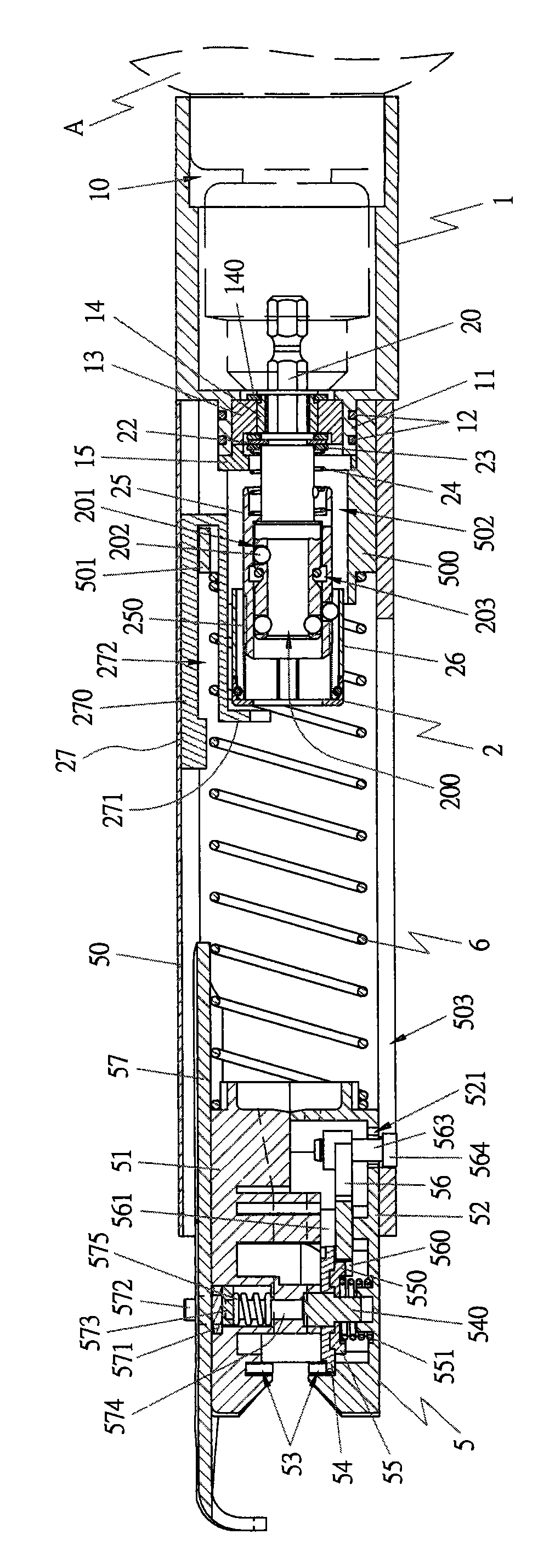
[0059] Such as figure 1 As shown, it is a cross-sectional view of the screw belt locking device of the present invention, which includes: a sleeve assembly 1, a torque release device 2, and a screw belt transmission device 5,

[0060] The sleeve assembly 1 is provided with a sleeve groove 10, and is connected with the power hand tool A through the sleeve groove 10, and the power hand tool A is used to drive the following components to operate.

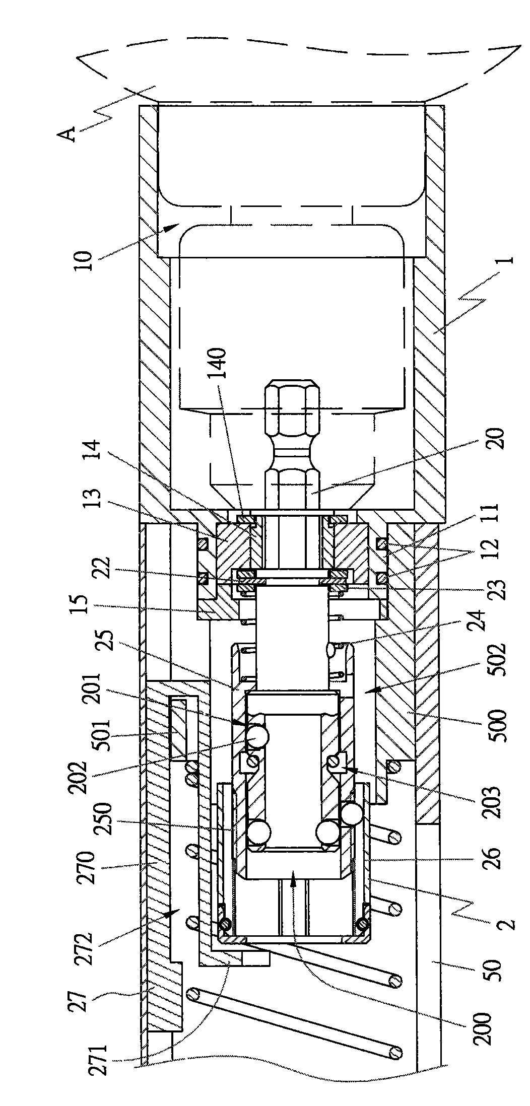
[0061] Such as figure 2 and 3 As shown, a bonding ring 11 with a smaller outer diameter is provided at the other end of the sleeve assembly 1, and a plurality of sealing rings 12 are provided on the surface of the bonding ring 11. The sealing rings 12 can be made of elastic plastic,...


PUM


Abstract

The invention discloses a screw tape locking device. The locking device comprises an assembly component, a torque force release device and a nail tape transmission device, wherein the assembly component and a power hand tool are connected into a whole; one end of the assembly component is provided with a coupling ring; the torque force release device is provided with a coupling rod part; one end of the coupling rod part is connected with the power hand tool; a drive component is arranged outside the torque force release device, and is driven by the nail tape transmission device; the nail tape transmission device is provided with a body; a rear stopper which is arranged inside the rear part of the body is connected with the assembly component, and the torque force release device is arranged at the rear end inside the body; and an elastic component is arranged between the nail tape transmission device and the torque force release device. When the screw tape locking device is used, a screw is locked in a locking object only by starting the power hand tool; after a locking depth is reached, the nail tape transmission device can be used to drive the torque force release device to release the torque force of a locking screwdriver head, so that the residual torque force of the locking screwdriver head can be prevented from damaging a locking groove of the screw, and the screw tape locking device can better meet practical application requirements.

Description

technical field [0001] The invention relates to a screw strap locking device, in particular to a screw strap locking device that prevents the residual torque of a screwdriver head from destroying a locking groove of a screw and makes the screw strap locking device more suitable for practical use. Background technique [0002] The device that can automatically dial the screw band has U.S. No. 5,284,074 patent (or the No. 201953 patent in Taiwan, China). When the rotating shaft of the dial rotates, the shifting teeth of the dial are used to drive the screw belt to move. [0003] Another example is the Chinese Taiwan New Patent Announcement No. 537124. The improvement mechanism of the screw feeder is provided with a pusher group, which utilizes the protruding teeth on the gear of the pusher group set inside the front end of the gun nozzle body to engage with the nail belt correspondingly. When the gear of the set rotates, it can drive the nail belt to move a displacement at th...

Claims


Application Information

Patent Timeline
IPC IPC(8): B25B23/04B25B23/00
Inventor 陈河田
Owner 陈河田
Why Eureka
Try Eureka