Diffraction optical element and optical pickup device

An optical pick-up device and laser technology, which is applied in the direction of beam guiding devices, optics, optical components, etc., can solve the problems of decreased precision, inability to recognize the signal recording surface of a double-layer disk, and difficulty in focus control, etc., and achieve the effect of simplifying the structure

Inactive Publication Date: 2013-03-06
MITSUBISHI ELECTRIC CORP
View PDF2 Cites 0 Cited by
  • Summary
  • Abstract
  • Description
  • Claims
  • Application Information

AI Technical Summary

Problems solved by technology

[0009] However, when the linear range of the focus error signal is reduced, focus control for CDs that allow a large disc surface wobble in the focus direction (that is, have a large focus shift allowable value) becomes difficult
[0010] Conversely, when the linear range of the focus error signal is increased, focus control for CD becomes easy, but the accuracy of focus control for Blu-ray discs and DVDs decreases, and each signal recording surface of a dual-layer disc cannot be recognized
[0011] In this way, since the depth of focus of the CD standard is about 7 times that of the Blu-ray standard, it is very difficult to set the linear range of the focus error signal that satisfies both standards

Method used


Image

  • Diffraction optical element and optical pickup device
  • Diffraction optical element and optical pickup device
  • Diffraction optical element and optical pickup device

Examples


Embodiment approach 1

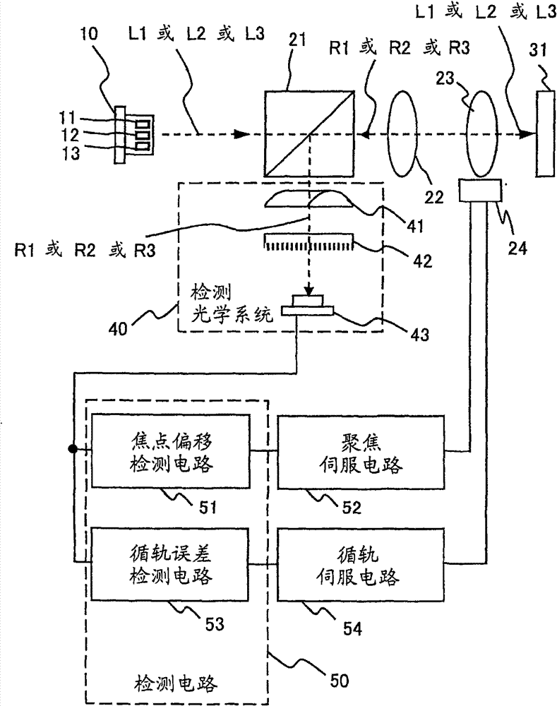
[0035] figure 1 It is a plan view schematically showing the structure of the optical pickup device according to Embodiment 1 of the present invention. Such as figure 1 As shown, the optical pickup device of the first embodiment has a semiconductor laser 10 as a laser light source, which excites a first laser L1 with a first wavelength as a center wavelength, and a second wavelength with a second wavelength longer than the first wavelength as the center wavelength. 2Laser L2, and third laser L3 with a third wavelength longer than the second wavelength as the center wavelength; beam splitter 21; used to make the laser light (L1 or L2 or L3) emitted from the semiconductor laser 10 into parallel light A collimator lens (collimator lens) 22; an objective lens 23, which focuses the laser light (L1 or L2 or L3) emitted from the collimator lens 22 on the optical disc 31; and a servo mechanism 24, which is used for focusing control of the objective lens 23 And tracking (tracking) cont...

Embodiment approach 2

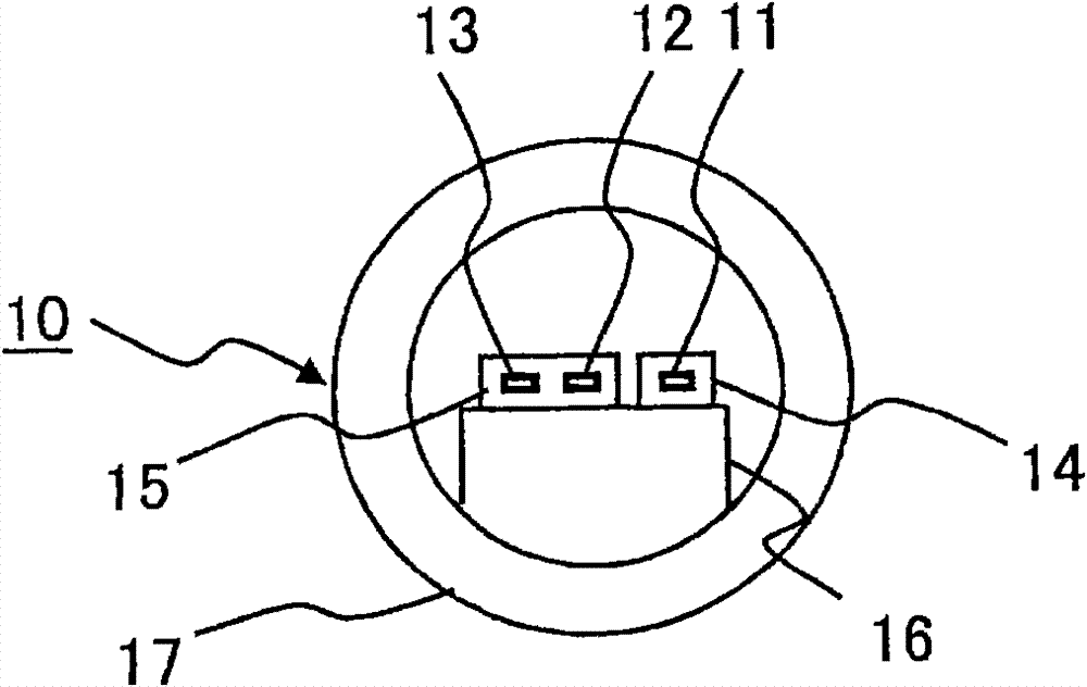
[0070] Figure 15 It is a front view showing another semiconductor laser 10a applicable to the optical pickup device of the second embodiment of the present invention. in figure 2 In the example, the semiconductor laser 10 in which the three laser excitation regions 11, 12, and 13 are arranged in a row on the heat dissipation member 16 is exemplified, but it can also be used Figure 15 As shown, the first semiconductor laser element 14a and the second semiconductor laser element 15a are laminated on the heat dissipation member 16. Among them, the case where the second semiconductor laser element 15a has two laser excitation regions is exemplified, but the present invention is not limited to this mode, and there may be three semiconductor laser elements. In addition, the optical pickup device of Embodiment 2 is the same as the optical pickup device of Embodiment 1 described above except for the above.


PUM


Abstract

An optical pickup with a simplified structure in which, according to the type of optical disc, diffracted light from three types of laser light can be directed efficiently onto a photodetector and appropriate focus control can be performed based on the signals detected by the photodetector, and a diffractive optical element that can be used in the optical pickup, which has a semiconductor laser 10 that can emit three types of laser light, a diffractive optical element 42 that diffracts the laser light reflected from the optical disc 31, and a single photodetector 43 that detects the diffracted light exiting the diffractive optical element 42. The diffractive optical element 42 is structured so that 0-order light is the maximal component of the diffracted light generated from each of two of three types of laser light, the two having close wavelengths (with a small wavelength difference), and +1-order light or −1-order light is the maximal component of the diffracted light generated from the remaining one type of laser light.

Description

Technical field [0001] The present invention relates to an optical pickup device that can correspond to three optical disc standards, and a diffractive optical element that can be mounted on the optical pickup device. Background technique [0002] As optical discs, there are CDs (compact discs) that use infrared lasers with a center wavelength of 0.78 μm to record or reproduce information, and DVDs that use red lasers with a center wavelength of 0.65 μm to record or reproduce information. (Digital versatile disc: digitalversatile disc). In addition, HD-DVD and Blu-ray discs (hereinafter collectively referred to as "blue laser discs" or "Blu-ray discs") that use a blue laser with a center wavelength of 0.405 μm to record or reproduce information are also beginning to be available Practical application. [0003] Generally, a recording and reproducing device for a blue laser disc is configured to be capable of recording or reproducing information for conventional DVDs and CDs. Rega...

Claims


Application Information

Patent Timeline
Patent Type & Authority Patents(China)
IPC IPC(8): G11B7/1353G11B7/1381G02B5/18G11B7/135
CPCG02B5/1842G11B7/1381G02B5/1861G02B5/1819G11B2007/0006G02B26/0808G11B7/1353
Inventor 篠田昌久松原大介中井贤也中原宏勋
Owner MITSUBISHI ELECTRIC CORP
Why Eureka
Try Eureka