Diffraction optical element and optical pickup device

A technology of diffractive optical elements and optical pick-up devices, applied in the direction of optical elements, diffraction gratings, beam guiding devices, etc., can solve the problems of decreased precision, difficulty in focus control, difficulty in the linear range of focus error signals, etc., and achieve the goal of simplifying the structure Effect

Inactive Publication Date: 2009-12-30
MITSUBISHI ELECTRIC CORP
View PDF2 Cites 0 Cited by
  • Summary
  • Abstract
  • Description
  • Claims
  • Application Information

AI Technical Summary

Problems solved by technology

[0009] However, when the linear range of the focus error signal is reduced, focus control for CDs that allow a large disc surface wobble in the focus direction (that is, have a large focus shift allowable value) becomes difficult
[0010] Conversely, when the linear range of the focus error signal is increased, focus control for CD becomes easy, but the accuracy of focus control for Blu-ray discs and DVDs decreases, and each signal recording surface of a dual-layer disc cannot be recognized
[0011] In this way, since the depth of focus of the CD standard is about 7 times that of the Blu-ray standard, it is very difficult to set the linear range of the focus error signal that satisfies both standards

Method used


Image

  • Diffraction optical element and optical pickup device
  • Diffraction optical element and optical pickup device
  • Diffraction optical element and optical pickup device

Examples


Embodiment approach 1

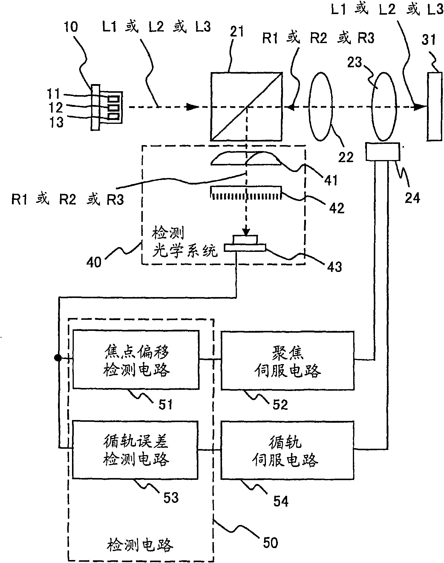
[0036] figure 1 It is a plan view schematically showing the configuration of the optical pickup device according to Embodiment 1 of the present invention. Such as figure 1 As shown, the optical pickup device of Embodiment 1 has: a semiconductor laser 10 as a laser light source, which excites a first laser light L1 having a first wavelength as a center wavelength, and a first laser light L1 having a second wavelength longer than the first wavelength as a center wavelength. 2 laser light L2, and a third laser light L3 having a third wavelength longer than the second wavelength as a center wavelength; a beam splitter 21; a laser beam (L1 or L2 or L3) emitted from the semiconductor laser 10 into parallel light Collimator lens (collimator lens) 22; Objective lens 23, it makes the laser light (L1 or L2 or L3) after emitting collimator lens 22 focus on the optical disk 31; And servo mechanism 24, it is used for carrying out the focus control of objective lens 23 and tracking cont...

Embodiment approach 2

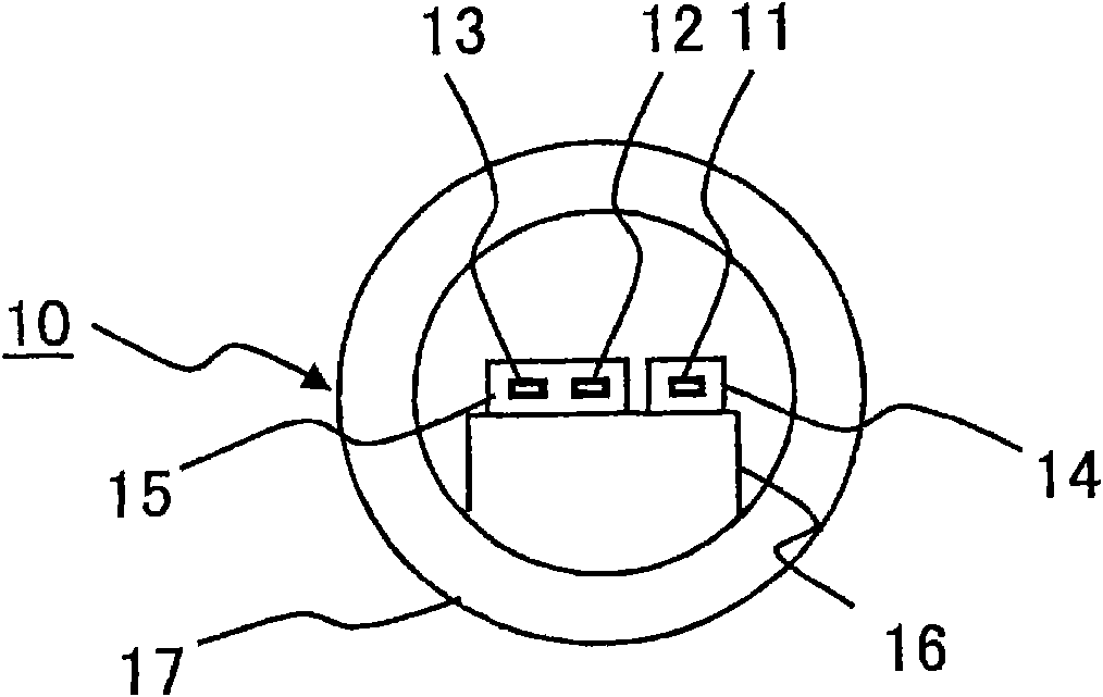
[0071] Figure 15 It is a front view showing another semiconductor laser 10 a applicable to the optical pickup device according to Embodiment 2 of the present invention. exist figure 2 In the above, the semiconductor laser 10 in which three laser excitation regions 11, 12, and 13 are arranged in a row on the heat dissipation member 16 is exemplified, but it is also possible to use Figure 15 As shown, the first semiconductor laser element 14 a and the second semiconductor laser element 15 a are stacked on the heat dissipation member 16 . Here, the case where the second semiconductor laser element 15a has two laser excitation regions was exemplified, but the present invention is not limited to this aspect, and the number of semiconductor laser elements may be three. In addition, the optical pickup device of Embodiment 2 is the same as the optical pickup device of Embodiment 1 above except for the above.


PUM


Abstract

A simply-structured optical pickup device in which the diffracted lights of three laser beams can be made efficiently to enter a single optical sensor, and proper focus control can be carried out according to the detection signal from the optical sensor, and a diffraction optical element used for such an optical pickup device are provided. The optical pickup device comprises a laser light source (10) capable of emitting three different laser beams, a diffraction optical element (42) for diffracting the reflected laser beams from an optical disk (31), and an optical sensor (43) for sensing thediffracted lights outputted from the diffraction optical element (42). The diffraction optical element (42) is composed of an optical member fabricated so that the zero-order diffracted light produced from each of the two laser beams whose wavelengths is close to each other (the difference between the wavelengths is small) may be the component having the greatest intensity, and the +1 order diffracted light or -1 order diffracted light produced from the other laser beam may be the component having the greatest intensity.

Description

technical field [0001] The present invention relates to an optical pickup device capable of supporting three types of optical disc standards, and a diffractive optical element mountable on the optical pickup device. Background technique [0002] As optical discs, there are CDs (compact discs) that record or reproduce information using infrared laser light with a center wavelength of 0.78 μm, and DVDs that use red laser light with a center wavelength of 0.65 μm to record or reproduce information. (Digital Versatile Disc: digitalversatile disc). In addition, HD-DVD and Blu-ray discs (hereinafter collectively referred to as "blue laser discs" or "Blu-ray discs") that record or reproduce information using a blue laser with a center wavelength of 0.405 μm have also begun to be obtained. practical application. [0003] Generally, a recording / reproducing device for a blue laser disc is configured to be capable of recording or reproducing information also on conventional DVDs and ...

Claims


Application Information

Patent Timeline
IPC IPC(8): G11B7/135G02B5/18G11B7/09
CPCG02B5/1842G11B7/1381G02B5/1861G02B5/1819G11B2007/0006G02B26/0808G11B7/1353
Inventor 篠田昌久松原大介中井贤也中原宏勋
Owner MITSUBISHI ELECTRIC CORP
Why Eureka
Try Eureka