Cradle type storage conveyor

A conveyor and cradle-type technology, which is applied in the field of cradle-type storage conveyors, can solve the problems of large conveying limitations, waste of storage materials, inability to use the gravity of the workpiece itself, and lack of storage functions, etc., to achieve the effect of reducing the swing range

Active Publication Date: 2018-01-12
NINGXIA KOCEL MACHINE TOOL ACCESSORIES
View PDF6 Cites 0 Cited by
  • Summary
  • Abstract
  • Description
  • Claims
  • Application Information

AI Technical Summary

Problems solved by technology

However, the above-mentioned chain conveyors have great conveying limitations and material storage waste:
[0003] (1) Since the accompanying tooling and the attached plate on the chain are fixed connections, and the relative position of the accompanying tooling and the attached plate is fixed, during the movement of the chain driven by the rotation of the sprocket, the accompanying tooling cannot use the gravity of the workpiece itself at the position of the sprocket and the lower layer Achieve the function of self-positioning on the accompanying tooling;
[0004] (2) In the chain running position where the accompanying tooling cannot realize the self-positioning of the workpiece, the material storage function of the accompanying tooling is missing

Method used


Image

  • Cradle type storage conveyor
  • Cradle type storage conveyor
  • Cradle type storage conveyor

Examples


Embodiment Construction

[0026] In order to make the technical means, creative features, goals and effects achieved by the present invention easy to understand, the present invention will be further described below in conjunction with specific embodiments.

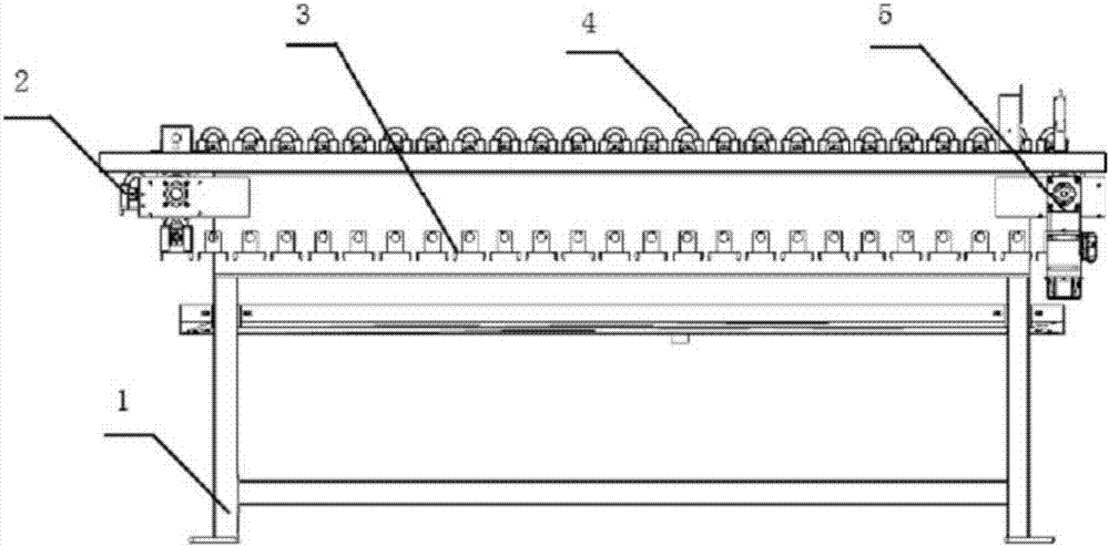
[0027] see figure 1 , the present invention provides a technical solution: a cradle-type storage conveyor, including a frame 1, a sprocket position area 2, a lower position area 3, an upper position area 4, a motor 5, a main body sheet metal 11 and a transmission shaft 12, The frame 1 is provided with a sprocket position area 2 , a lower position area 3 and an upper position area 4 .

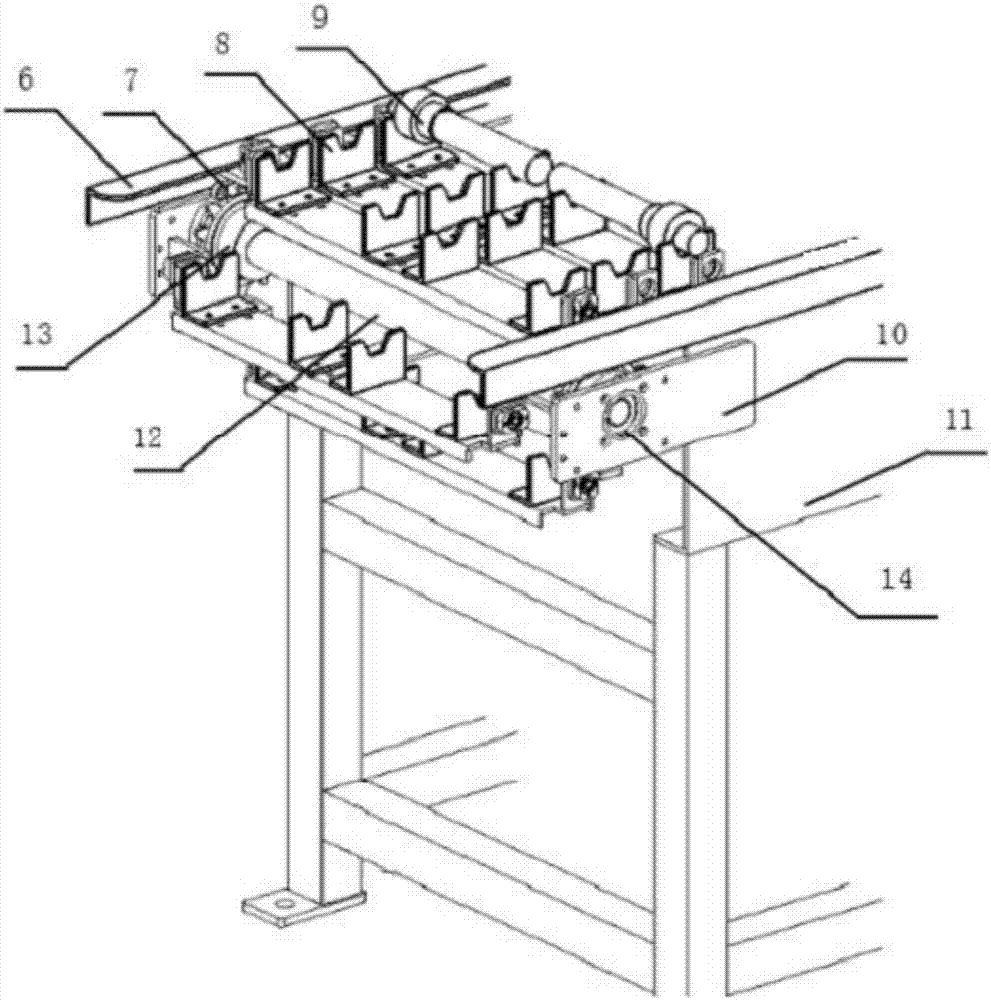
[0028] see figure 2 , the main body sheet metal 11 is installed on the side of the frame 1, the end of the main body sheet metal 11 is installed with a mounting plate 10, the bearing with seat 14 is installed on the mounting plate 10, the transmission shaft 12 is installed in the bearing with seat 14, and the transmission shaft 12 Sprocket 13 is arranged at both ...


PUM


Abstract

The invention provides a cradle type storage conveyor. The cradle type storage conveyor includes a rack, a chain wheel position region, a lower position region, an upper position region, a motor, a main metal plate, and a transmission shaft; chain plates are arranged on an inner side of a guide metal plate; L-shaped supporting metal plates are arranged on the chain plates; axial long-bar-shaped holes are formed in the chain plates; chain plate connectors are arranged on two sides of the chain plates; the chain plate connectors are used for fixedly connecting the chain plates and attaching plate connectors; a round hole is formed in each of folded edges at two ends of the chain plates; outer cylindrical surfaces of key-free bushings and the round holes are connected through a clearance fit;the chain plates, the L-shaped supporting metal plates, rotation shafts, the chain plate connectors, the key-free bushings, second bearings with seats and shaft clamping springs form an accompanyingtooling. The beneficial effects of the invention are that on the basis of the action of gravity of a work piece, the design demand of the accompanying tooling in the chain wheel position area can be met by designing and calculating a geometrical relation between the center of gravity and the rotation axis of the accompanying tooling; and a simple structure of the accompanying tooling can be achieved through the key-free bushings.

Description

technical field [0001] The invention is a cradle type storage conveyor, which belongs to the field of mechanical equipment. Background technique [0002] Through search and search, it is found that in the field of warehousing and logistics, the bar is often conveyed by a chain conveyor with tooling. The motor drives the main shaft, and the main shaft drives the sprocket to rotate, realizing the equidistant intermittent movement of the chain driven by the teeth on the sprocket, and fulfilling the requirements of transporting the workpiece to the correct position at the correct time and with the correct posture. However, the above-mentioned chain conveyors have great conveying limitations and material storage waste: [0003] (1) Since the accompanying tooling and the attached plate on the chain are fixed connections, and the relative position of the accompanying tooling and the attached plate is fixed, during the movement of the chain driven by the rotation of the sprocket, t...

Claims


Application Information

Patent Timeline
Patent Type & Authority Applications(China)
IPC IPC(8): B65G17/06B65G17/46B65G17/42
Inventor 齐亚文王宝国赵亚宁
Owner NINGXIA KOCEL MACHINE TOOL ACCESSORIES
Why Eureka
Try Eureka