Portable display

A display, portable technology, applied in the field of portable displays, to achieve the effect of optimizing angle and arrangement, reducing height, reducing height

Pending Publication Date: 2022-03-22
NEW VISION MICROELECTRONICS INC
View PDF6 Cites 0 Cited by
  • Summary
  • Abstract
  • Description
  • Claims
  • Application Information

AI Technical Summary

Problems solved by technology

[0003] With the rapid development of high-tech, the requirements for portable display devices are getting higher and higher. Display devices are required to meet high resolution or ultra-high resolution, larger display area, narrower display panel frame, and lower power consumption. Consumption, lower cost, bring great challenges to design engineering and production process

Method used


Image

  • Portable display
  • Portable display
  • Portable display

Examples


Embodiment 1

[0018] A portable display, the display includes: a display panel, a driver chip and a flexible circuit board; the display panel includes: a display area, a frame of the display panel and a driver chip binding area; the driver chip is placed in the driver chip binding area Inside, part of the driver chip Source signal output connection line in the driver chip or a mixed arrangement of the driver chip Source output array in the driver chip is located under the driver chip and close to the lower frame side of the display panel, and is located between the driver chip gate output array and the driver chip input pin. between arrays.

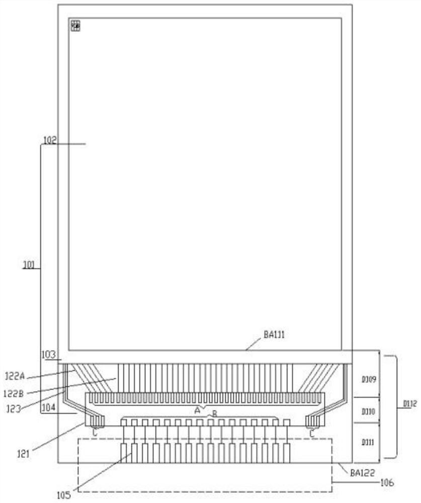
[0019] refer to figure 1 , figure 1 It is a schematic structural diagram of an existing traditional portable display panel. The portable display is a traditional COG (chiponglass) binding process technology. The portable display includes a display panel 101, a driver chip 121, and a flexible circuit board 106, wherein the display panel 101 includes a ...

Embodiment 2

[0022] On the basis of the previous embodiment, more than 20% of the driver chip Source signal output connection lines in the driver chip are arranged in a mixed manner and placed under the driver chip near the side of the frame of the display panel, between the gate output array of the driver chip and the input pin of the driver chip. between arrays.

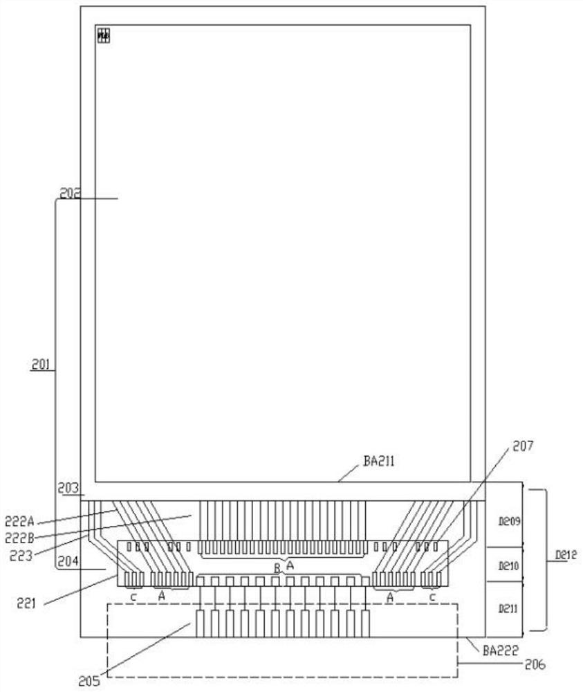
[0023] refer to figure 2 , figure 2 In order to implement the present invention, a kind of portable display panel narrow frame driver chip display panel technical structure schematic diagram, the invention portable display narrow lower frame driver chip display panel is a traditional COG (chiponglass) binding process technology, the invention portable narrow lower frame display includes A display panel 201, a driver chip 221, and a flexible circuit board 206 are provided, wherein the display panel 201 includes a display area 202, a display panel frame 203, and a driver chip binding area 204. The driver chip binding area 204...

Embodiment 3

[0026] On the basis of the previous embodiment, more than 20% of the driver chip Source output arrays in the driver chip are mixed and arranged under the driver chip and close to the lower frame side of the display panel, and are located between the driver chip gate output array and the driver chip input pin array. between.

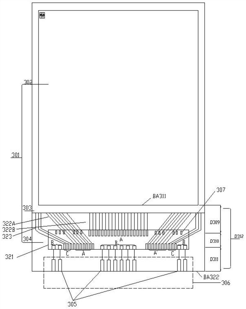
[0027] refer to image 3 ,exist image 3 In another implementation example shown, more than 30% of the driver chip Source output signal of the driver chip 221 or the mixed arrangement of the touch pin array A is placed under the driver chip in the direction of the edge BA222 of the display panel, which greatly optimizes the driver chip Gate. The fanout angle and arrangement of the output side line 223 and the output connection line 222A of the driver chip Source (including the touch pin) reduces the total height D212 from the side BA211 of the display area of ​​the display panel to the input pin of the driver chip. In this implementation case, more than...


PUM


Abstract

The invention belongs to the technical field of displays, and particularly relates to a portable display. The display comprises a display panel, a driving chip and a flexible circuit board, the display panel comprises a display area, a display panel frame and a driving chip binding area, the driving chip is arranged in the driving chip binding area, and a part of driving chip Source signal output connecting lines in the driving chip or a part of driving chip Source output arrays in the driving chip are arranged on one side, close to the frame of the display panel, of the lower portion of the driving chip in a mixed mode and located between the driving chip gate output array and the driving chip input pin array. The display panel is suitable for display panels made of various materials, the size of a non-display area can be reduced, meanwhile, the narrow frame requirement of the portable display is greatly improved, the attractive and portable effects are achieved, and cost is saved.

Description

technical field [0001] The invention belongs to the technical field of displays, and in particular relates to a portable display. Background technique [0002] A display (display, screen) is an I / O device belonging to a computer, that is, an input and output device. It is a display tool that displays a certain electronic file on the screen through a specific transmission device and then reflects it to the human eye. It can be divided into CRT, LCD and other types. [0003] With the rapid development of high-tech, the requirements for portable display devices are getting higher and higher. Display devices are required to meet high resolution or ultra-high resolution, larger display area, narrower display panel frame, and lower power consumption. Consumption and lower cost bring great challenges to design engineering and production process. Contents of the invention [0004] In view of this, the main purpose of the present invention is to provide a portable display, which...

Claims


Application Information

Patent Timeline
Patent Type & Authority Applications(China)
IPC IPC(8): G09F9/30
CPCG09F9/30
Inventor 温永良肖宏周剑
Owner NEW VISION MICROELECTRONICS INC
Why Eureka
Try Eureka