
Encoding apparatus and decoding apparatus

A technology of an encoding device and a decoding device, applied in the fields of encoding devices and decoding devices, can solve problems such as reducing encoding efficiency

Inactive Publication Date: 2014-05-07
FUJITSU LTD
View PDF9 Cites 0 Cited by
  • Summary
  • Abstract
  • Description
  • Claims
  • Application Information

AI Technical Summary

Problems solved by technology

Such direct vectors are not maximum plausible, thus reducing coding efficiency

Method used


Image

  • Encoding apparatus and decoding apparatus
  • Encoding apparatus and decoding apparatus
  • Encoding apparatus and decoding apparatus

Examples


no. 1 approach

[0033] [Overview of Encoding Device and Decoding Device]

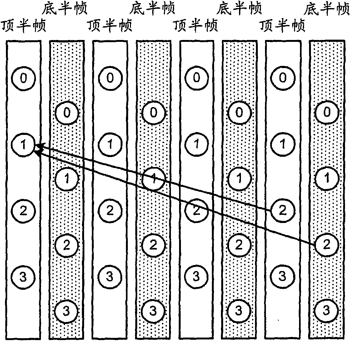
[0034] refer to Figures 1A to 1C The outline of the encoding device and the decoding device according to the first embodiment of the present invention will be described. Figures 1A to 1C Outlines of the encoding device and the decoding device according to the first embodiment are depicted.

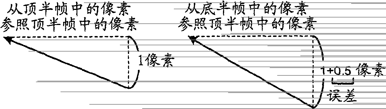
[0035] Such as Figure 1A As shown, if a picture with a field structure is coded in direct mode with reference to pixels with opposite parity, an error corresponding to this difference in parity occurs in the vector. For example, if Figure 1A As shown in , if pixel "2" in one top field (Top_field) refers to pixel "1" in another top field (Top_field), the vertical component of the vector is derived from "2" - "1" "one pixel" (see Figure 1B ), while the value of the vertical component of this vector is correctly calculated as "-4 (1 pixel / 0.25 pixel)".

[0036] For example, if Figure 1A As shown, if pixel "2" in a bottom ...


PUM


Abstract

An encoding apparatus (100) having a direct mode as a prediction mode, when a pixel with opposite parity from a top field to a bottom field, for example, is referred to for obtaining a reference vector in the direct mode, performs correction by adding or subtracting a value corresponding to a half pixel to or from a value of the obtained reference vector. The encoding apparatus (100), when a pixel with opposite parity is referred to for obtaining a first and a second direct vector by temporally scaling the corrected reference vector, performs correction by adding or subtracting a value corresponding to a half pixel to or from values of the obtained direct vectors.

Description

technical field [0001] Embodiments discussed herein relate to encoding devices and decoding devices. Background technique [0002] H.264 and Part 10 (AVC: Advanced Video Coding) of Moving Picture Experts Group-4 (MPEG-4) have been standardized as methods for encoding moving image data, and are attracting attention. Since H.264 and Part 10 (AVC) of MPEG-4 are technically the same, it will be referred to as H.264 / AVC below. [0003] H.264 / AVC has five coding modes (including: intra prediction, forward prediction, backward prediction, bi-directional prediction and direct mode) as the coding mode of a bi-directional predictive picture (B-picture). In particular, a newly added mode is a direct mode, which is a method focusing on the continuity of moving image data, based on temporally or spatially adjacent macroblocks (macroblock) motion vector determines the motion vector for the current macroblock. [0004] now refer to Figure 9 To describe the principle of the temporal dir...

Claims


Application Information

Patent Timeline
Patent Type & Authority Patents(China)
IPC IPC(8): H04N19/513H04N19/13H04N19/61H04N19/89H04N19/105H04N19/134H04N19/139H04N19/159H04N19/16H04N19/50H04N19/503H04N19/51H04N19/573H04N19/593H04N19/60H04N19/85H04N19/91
CPCH04N7/26127H04N19/00224H04N19/00024H04N19/00715H04N19/00721H04N19/0063H04N19/00696H04N19/00157H04N19/00006H04N19/00781H04N19/10H04N19/105H04N19/14H04N19/16H04N19/52H04N19/573H04N19/61H04N19/523H04N19/577H04N19/51
Inventor 屋森章弘岛田智史中川章
Owner FUJITSU LTD
Learn More