
Video image signal coding method and device for predicting macro block code length

An encoding method and technology of an encoding device are applied in the field of video image signal encoding and device for predicting the code length of a macroblock, and can solve the problems of reduced encoding efficiency and the like

Inactive Publication Date: 2004-08-18
MITSUBISHI ELECTRIC CORP
View PDF0 Cites 0 Cited by
  • Summary
  • Abstract
  • Description
  • Claims
  • Application Information

AI Technical Summary

Problems solved by technology

[0099] However, in the conventional encoding device 1 based on the MPEG-4 standard, as described above, when there is a length limitation on the video packets output from the variable length encoding circuit 15 in bit stream form, if sufficient consideration is not given to the video information The control of the code length of the packet is simply based on the judgment of whether the code length is above the specified value to generate the next video information packet, and it is necessary to re-predict and encode the excess video image signal, so there is a problem of making the coding efficiency Lowering the problem

Method used


Image

  • Video image signal coding method and device for predicting macro block code length
  • Video image signal coding method and device for predicting macro block code length
  • Video image signal coding method and device for predicting macro block code length

Examples


Embodiment Construction

[0120] Hereinafter, the present invention will be described based on the illustrated embodiments.

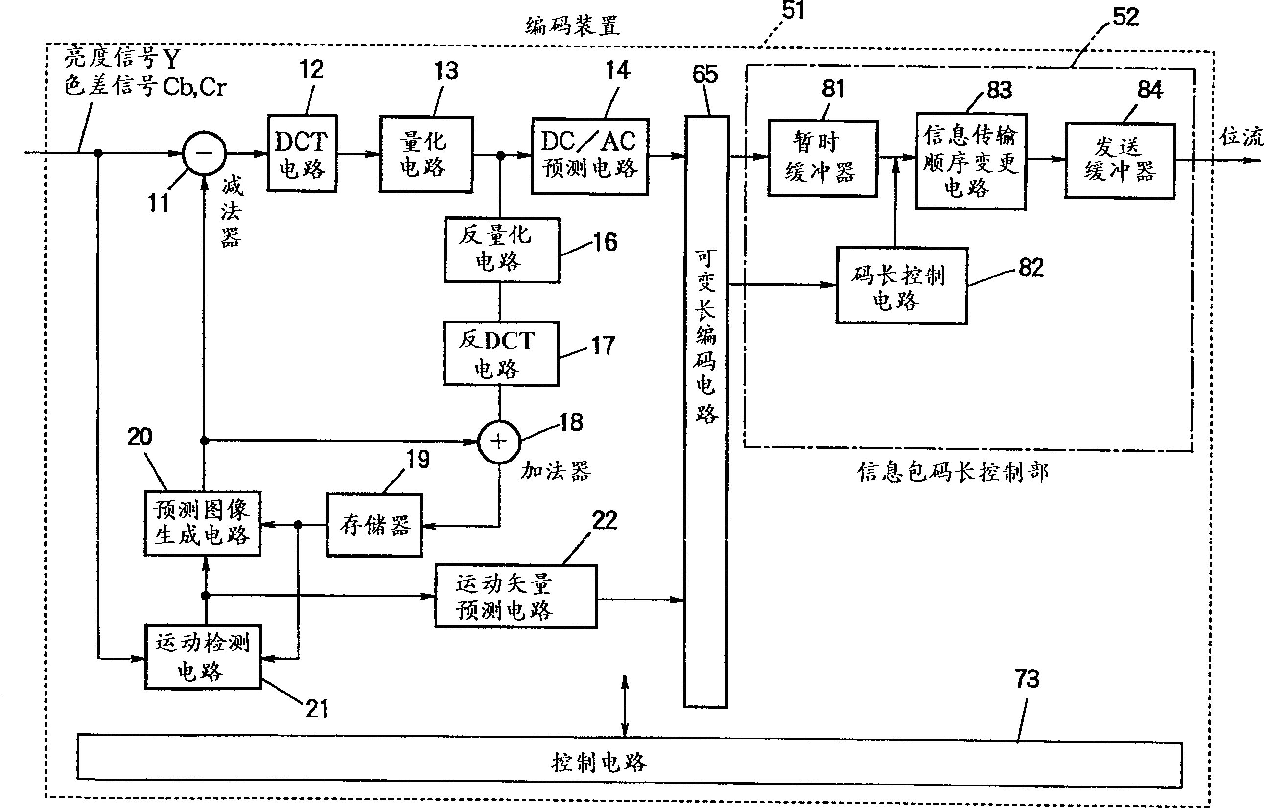
[0121] figure 1 is a diagram showing an encoding device 51 used as an embodiment of the present invention. exist figure 1 In FIG. 8, the same code|symbol is attached|subjected to the part which has the same function as the conventional encoding apparatus 1 shown in FIG. 8, and repeated description is abbreviate|omitted.

[0122] figure 1 The main difference between the coding device 51 and the coding device 1 shown in FIG.

[0123] The information packet code length control part 52 includes: a temporary buffer 81, which is used to temporarily store the code output from the variable-length encoding circuit 65; an information transmission sequence change circuit 83, which is performed by changing the code order stored in the temporary buffer. Data division; Transmission buffer 84, adds header etc. to the inputted code and outputs video information packet with bit stream for...


PUM


Abstract

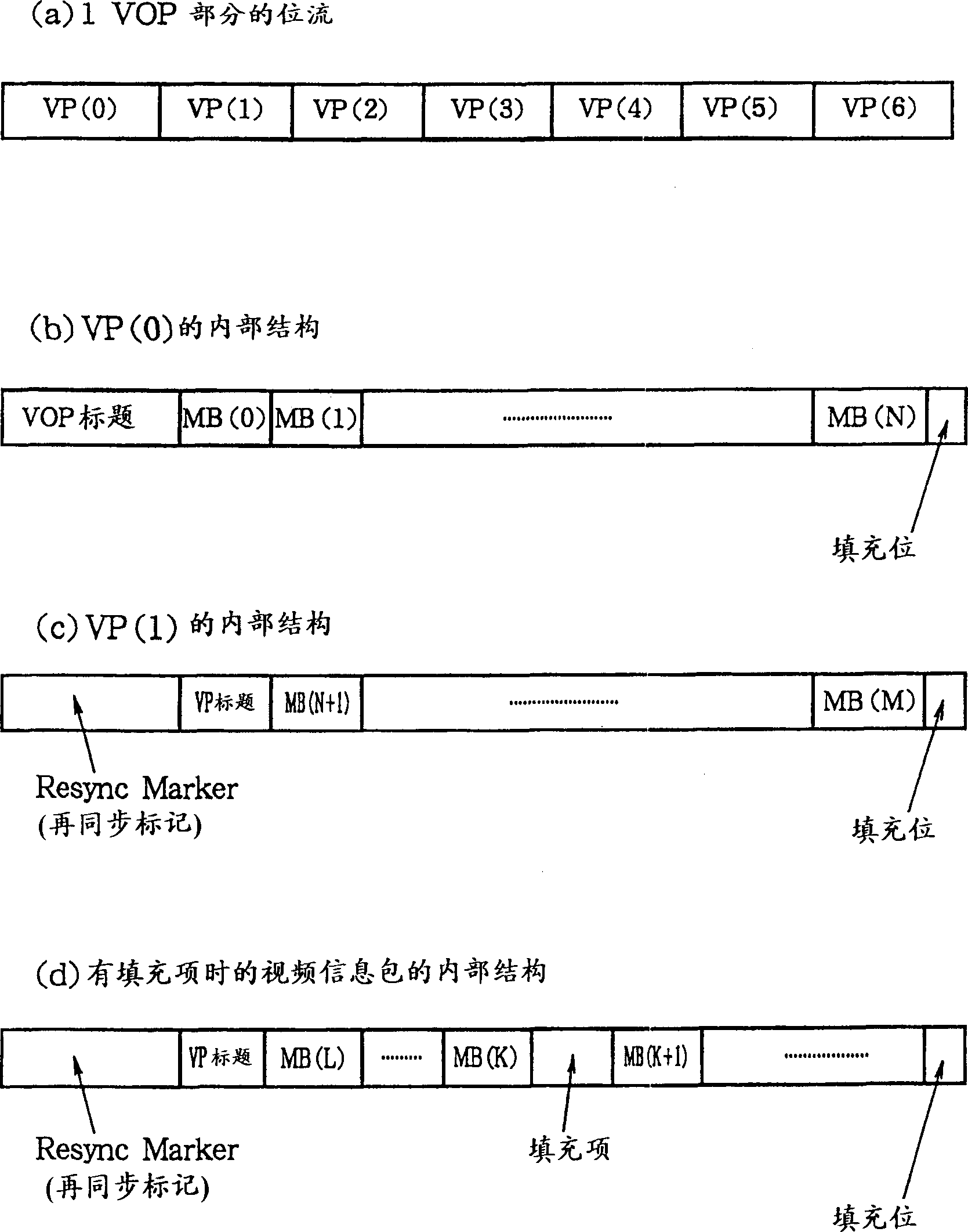
As the video signals of macroblocks are coded, they are stored in a buffer. When the total code length of the stored macroblocks exceeds a predetermined value, all but the most recently coded macroblock are output from the buffer as a video packet, and the most recently coded macroblock is coded again. To minimize this occurrence, when each coded macroblock is stored, the code length of the next macroblock is predicted and added to the total length, and if the resulting sum exceeds the predetermined value, all of the coded macroblocks stored in the buffer are output as a video packet.

Description

technical field [0001] The present invention relates to an encoding method and encoding device for encoding a plurality of macroblock video image signals and generating a video information packet whose code length is below a specified value based on the encoded video image signals. After the video image signal is blocked, the code length of the video information packet will be output until the code length of the macroblock video image signal after the previous encoding is used as the video information packet and the coded macroblock video image signal after this encoding will be regenerated. Encoded encoding device. Background technique [0002] In many video coding systems, a picture is divided into rectangular blocks and each block is coded using spatially adjacent blocks in the same picture. [0003] For example, a block may be coded by predicting the block's content from the coded content of neighboring blocks and coding the difference between the predicted content and ...

Claims


Application Information

Patent Timeline
Patent Type & Authority Patents(China)
IPC IPC(8): H04N5/92G06T9/00H03M7/30H03M7/36H03M7/40H04N19/102H04N19/105H04N19/115H04N19/13H04N19/15H04N19/176H04N19/196H04N19/423H04N19/50H04N19/51H04N19/57H04N19/60H04N19/625H04N19/69H04N19/91
CPCH04N7/26186H04N19/00327H04N7/26244H04N7/50H04N7/26324H04N19/152H04N19/176H04N19/188H04N19/194H04N19/61
Inventor 中尾贵史幡野喜子贵岛淳子杉山和宏
Owner MITSUBISHI ELECTRIC CORP
Learn More