
A non-return valve

A technology of check valves and ball valves, applied in the direction of control valves, valve devices, functional valve types, etc.

Inactive Publication Date: 2010-03-31
ITT MFG ENTERPRISES LLC
View PDF0 Cites 6 Cited by
  • Summary
  • Abstract
  • Description
  • Claims
  • Application Information

AI Technical Summary

Problems solved by technology

Even if a faster response is achieved, it is not necessarily fast enough to cause more serious problems

Method used


Image

  • A non-return valve
  • A non-return valve
  • A non-return valve

Examples


Embodiment Construction

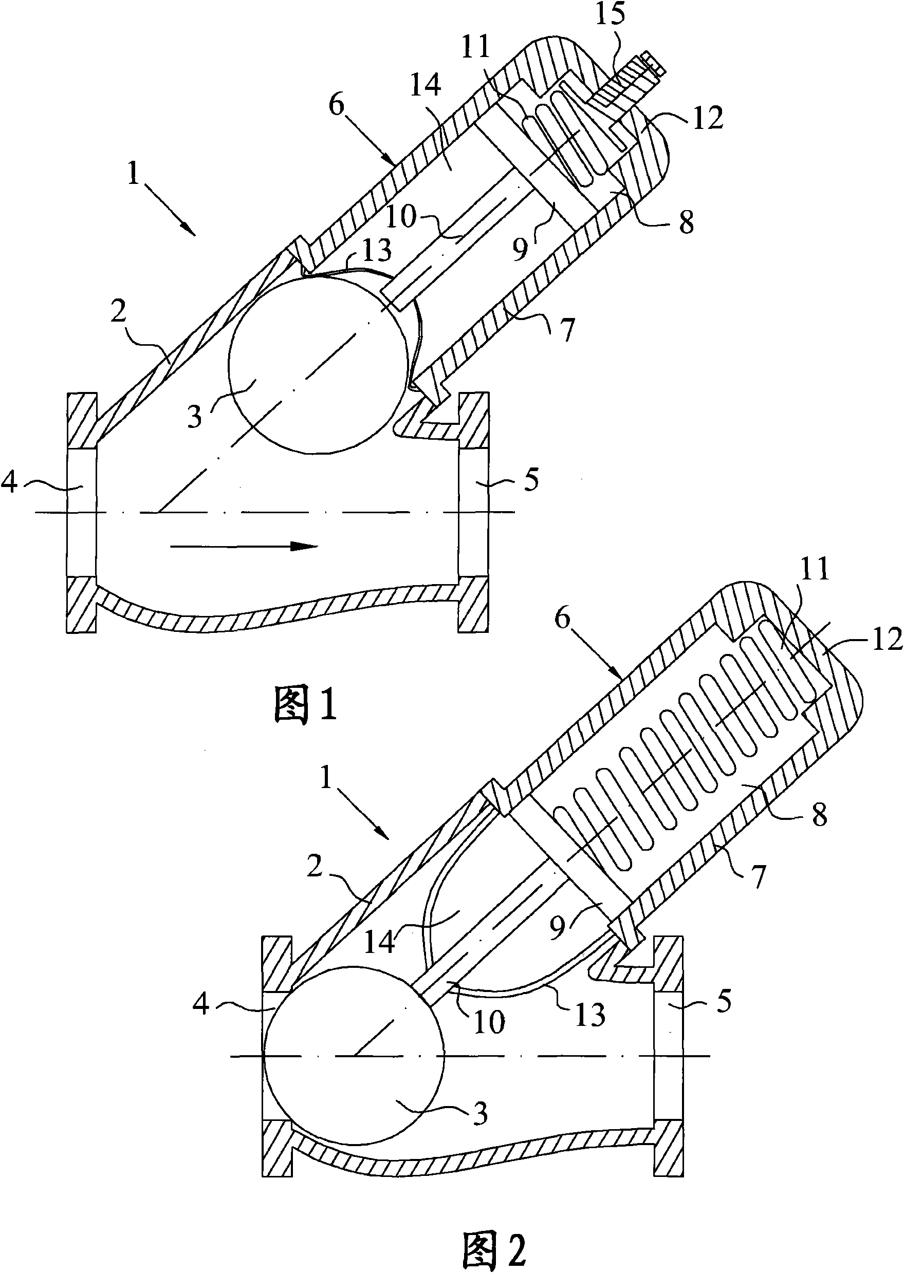
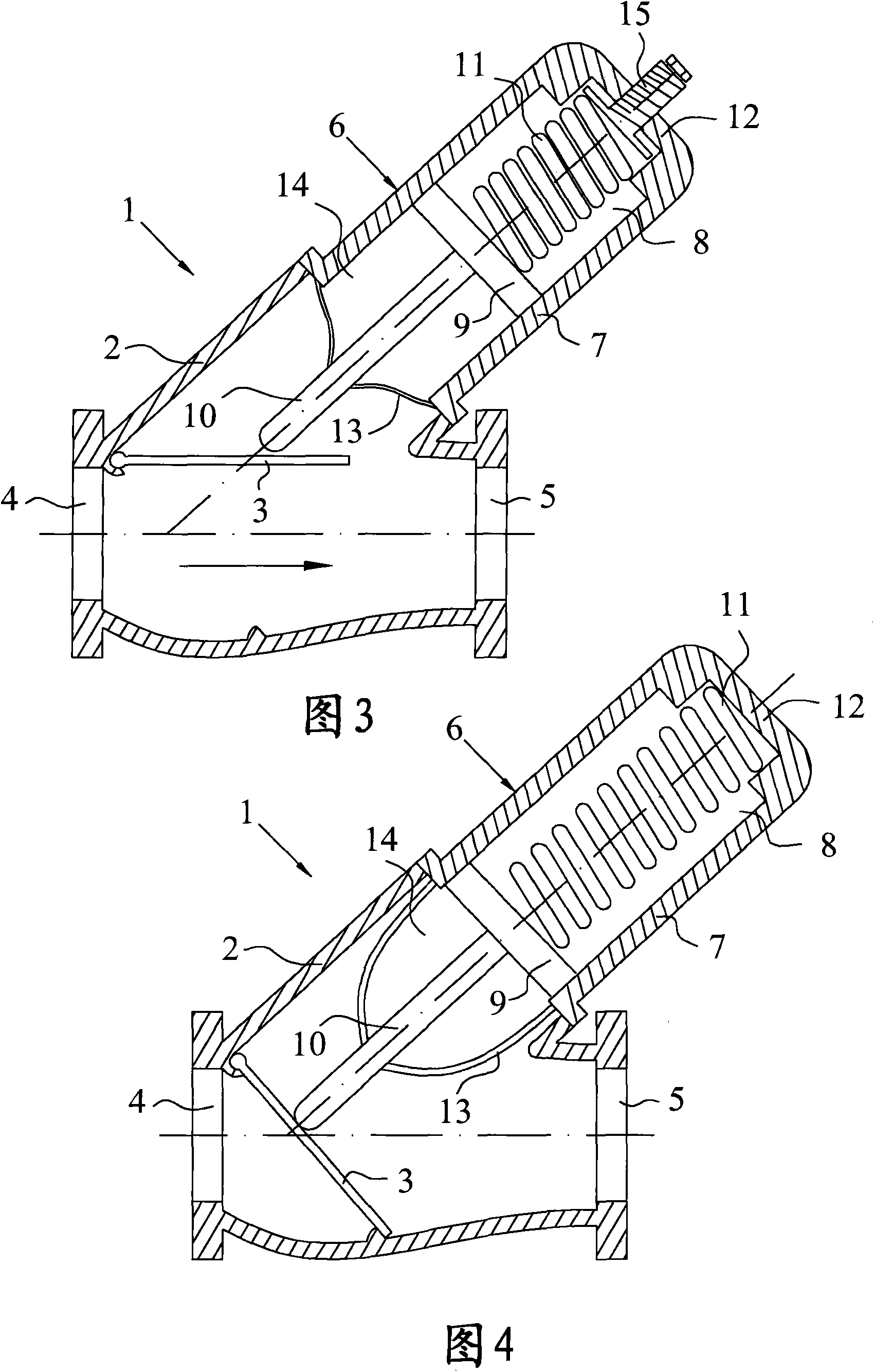
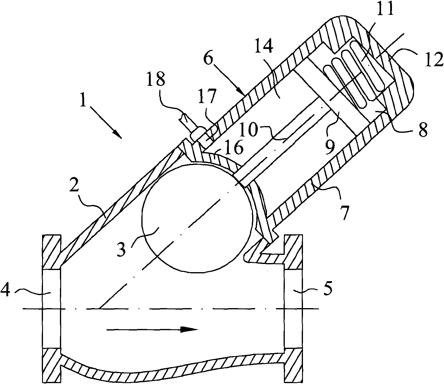
[0018] first reference figure 1 and 2 , which shows a first embodiment of the check valve 1 of the invention. The check valve 1 includes a valve housing 2 and a valve member 3 . The valve housing 2 defines the flow path of the liquid, the pump (not shown) in figure 1 Pump liquid in the direction of the arrow shown. Preferably, the check valve 1 and the pump are part of a waste water piping system (not shown). The pump is connected to the inlet port 4 of the check valve 1 by any suitable pipe (not shown) such as an outlet pipe, other suitable pipes (not shown) are connected to the outlet port 5 of the check valve 1 and may extend to the piping system main pipeline (not shown). in accordance with figure 1 and 2 In the embodiment shown, the valve member 3 consists of a ball which is freely movable between a first position and a second position, wherein in the first position according to figure 2 The flow path in the valve housing 2 is blocked and liquid flow in the first...


PUM


Abstract

The present invention relates to anon-return valve (1) for a liquid piping system, comprising a valve housing (2) and a valve member (3), which is movable between a first position, in which a flow path is blocked, and a second position, in 5 which the flow path is unblocked. The non-return valve (1) comprises a non-return valve attachment (6) comprising a housing (7), a piston assembly (9, 10) andan energy storing means (11), the piston assembly being axially movable in relation to said housing (7) between a first active position, 10 and a second position. In said second position the fluid pressure of said liquid drives the piston assembly against the action of the energy storing means (11) away from said first position, such that the valve member (3) is movable into said second positionof the valve member (3).

Description

technical field [0001] The present invention relates generally to the field of check valves for liquid piping systems. Further, the invention relates in particular to the field of non-return valves for waste water piping systems. A check valve includes a valve housing that defines a flow path for a liquid, and a valve member that is movable under the flow of the liquid between a first position and a second position in which flow The path is blocked and liquid flow in a first direction is blocked, and in the second position the flow path is unblocked and liquid flow in an opposite second direction is permitted. A check valve is provided with a check valve attachment comprising a housing, a piston assembly axially movable relative to the housing between a first position and a second position, and an energy storage device. Background technique [0002] In domestic and / or industrial applications, some products are connected to common waste water plumbing systems. Each product...

Claims


Application Information

Patent Timeline
Patent Type & Authority Applications(China)
IPC IPC(8): F16K15/03F16K15/04F16K15/06
CPCF16K15/044F16K15/033F16K15/1821F16K15/1823F16K15/063F16K2200/303
Inventor 罗兰·斯文松马丁·拉尔森维克托·卡尔松
Owner ITT MFG ENTERPRISES LLC
Learn More