Heat heat transferring member for a solder handling device, an electric iron and electric solder removing tool

A technology for processing devices and heat-conducting components, which is applied in the direction of soldering irons, electric heating devices, auxiliary devices, etc., and can solve problems such as stagnant airflow and inability to form surface modification layers

Active Publication Date: 2010-04-28
HAKKO CO LTD +1
View PDF7 Cites 6 Cited by
  • Summary
  • Abstract
  • Description
  • Claims
  • Application Information

AI Technical Summary

Problems solved by technology

However, since the hole formed in the heat conductor for accommodating the heating element is a bottomed hole (a hole that does not penetrate) that is deep in depth from the base end of the heat conductor, the air flow necessary for surface modification treatment will be reduced. Stagnated inside the pores, unable to form a uniform surface modification layer

Method used


Image

  • Heat heat transferring member for a solder handling device, an electric iron and electric solder removing tool
  • Heat heat transferring member for a solder handling device, an electric iron and electric solder removing tool
  • Heat heat transferring member for a solder handling device, an electric iron and electric solder removing tool

Examples


no. 1 Embodiment approach

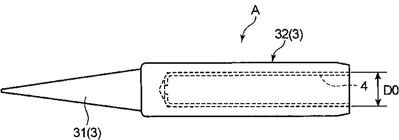
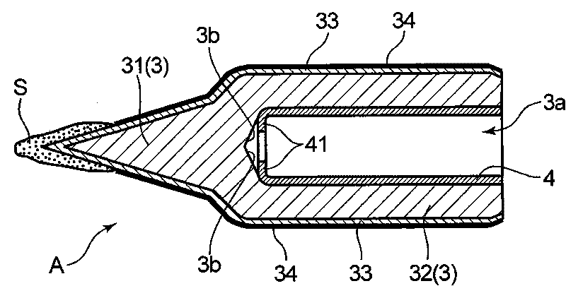
[0054] refer to figure 1 and figure 2 The thermal conductor 3 of the thermally conductive member A for a brazing processing apparatus according to the first embodiment uses copper as a base material, and has an integrated tapered tip portion 31 and a thermally conductive sleeve portion 32 that holds the heater 5 . The tip portion 31 constitutes a soldering iron tip for soldering. A bottomed hole 3 a that accommodates and holds the heater 5 is formed in the heat transfer sleeve portion 32 . The hole 3a is a cylindrical space with a diameter D0 that opens to the side opposite to the tip portion 31 side.

[0055] On the outer surface layer portion of the thermal conductor 3, in order to prevent the copper serving as the base material from being dissolved into molten solder, that is, so-called erosion by solder, an iron plating layer with a thickness of about 300 μm is formed on the surface of the base material. 33. In addition, in order to prevent corrosion of the surface of...

no. 2 Embodiment approach

[0077] In the first embodiment, the alumina film of the pipe for brazing treatment equipment is surface-modified by aluminizing treatment by the powder infiltration method, and then reacts with oxygen in the atmosphere to form a film naturally. In this regard, the second embodiment The aluminum oxide film of the tube of this method is surface-modified by aluminizing treatment by a slurry coating method, and then reacts with oxygen in the atmosphere to form a film naturally.

[0078] The slurry coating method is a kind of diffusion infiltration treatment method, which is to apply a slurry-like mixture mixed with aluminum powder, an activator and a binder to the object to be treated, and then heat treatment at high temperature in an inert gas environment method (refer to US Pat. No. 7,030,339). By modifying the surface of the cylindrical base material by this slurry coating method, the surface treatment can be performed using a small-scale facility without requiring a large-scal...

no. 3 Embodiment approach

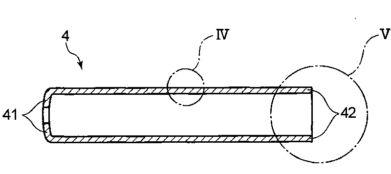
[0084] In the first and second embodiments, as Figure 5A , Figure 5B As shown, the rear end of the tube 4 is in a state without special processing, but it may be Figure 10A , Figure 10B As shown, the shape of the rear end portion of the pipe 4 is processed into a shape in which the cross section of the rear end portion is a quadrangle (an example of a polygon).

[0085] Figure 10A , Figure 10B The rear end of the pipe 4 is processed into a square shape. The length L1 between the opposite sides of the square is set smaller than the inner diameter D0 of the hole 3a formed in the thermal conductor 3 (refer to figure 1 ), and further, the diameter D2 of the circumscribed circle 4D of the square is set slightly larger than the inner diameter D0 of the hole 3a formed in the thermal conductor 3 . Assuming that the outer diameter of the central portion in the longitudinal direction of the pipe 4 is D1, the relationship of D2>D1≥D0>L1 holds.

[0086] Figure 10A , Figur...


PUM

PropertyMeasurementUnit
thicknessaaaaaaaaaa
thicknessaaaaaaaaaa
particle diameteraaaaaaaaaa

Abstract

A heat transferring member for a solder handling device, an electric iron with the heat transferring member and an electric solder removing tool with the heat transferring member are disclosed. The heat transferring member comprises a heat transfer body for melting solder, and a pipe inserted into a hole formed in the heat transfer body, wherein heat from a heating member is conducted to the heattransfer body. The pipe includes a tubular-shaped substrate made of copper or copper alloy, and an aluminum oxide film formed at least on a peripheral surface of the tubular-shaped substrate. Thus the heat transferring member can prevent the conducting member from being oxidized and keep high heat transfer efficiency.

Description

technical field [0001] The present invention relates to a heat-conducting member for a brazing processing apparatus used for brazing by a soldering iron brazing method, an electric soldering iron having the heat-conducting member, and an electric soldering tool having the heat-conducting member. Background technique [0002] Conventionally, in the electrical and electronic industry, the connection and joining of electronic components have been generally performed by a soldering method. [0003] Soldering methods include fluid soldering, reflow soldering, and soldering iron soldering. Among them, fluid soldering involves immersing a printed circuit board on which electronic components are mounted in molten solder, or directly immersing a solder joint in molten solder. A method of using a solder bath in a jet of molten solder; the reflow soldering method is to apply a solder paste to a printed circuit board by screen printing in advance to form a pattern, and after mounting su...

Claims


Application Information

Patent Timeline
Patent Type & Authority Applications(China)
IPC IPC(8): B23K3/08B23K3/03
CPCB23K3/025B23K3/0471B23K3/0369B23K3/0315B23K3/02B23K3/04C23C24/06
Inventor 寺冈巧知长濑隆
Owner HAKKO CO LTD
Why Eureka
Try Eureka